
An adaptive movable conductive connection mechanism

A conductive connection and adaptive technology, applied in the direction of electrical components, contact engagement, etc., to achieve the effect of reducing conductive contact area, reducing contact resistance, and large contact area

Active Publication Date: 2019-03-01
希捷爱斯(上海)电气有限公司
View PDF5 Cites 0 Cited by
  • Summary
  • Abstract
  • Description
  • Claims
  • Application Information

AI Technical Summary

Problems solved by technology

[0003] The technical problem to be solved by the present invention is to provide an adaptive movable conductive connection mechanism for the above-mentioned technical problems existing in the conductive contact of the existing knife switch. The defect of poor contact of contacts caused by parts processing or installation errors

Method used


Image

  • An adaptive movable conductive connection mechanism
  • An adaptive movable conductive connection mechanism
  • An adaptive movable conductive connection mechanism

Examples


Embodiment Construction

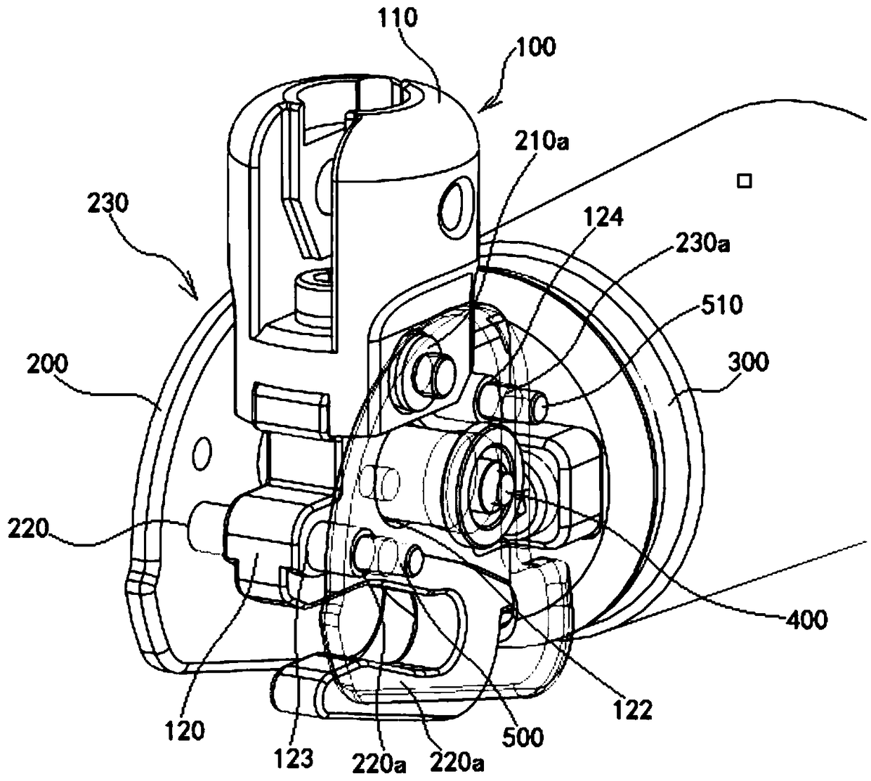
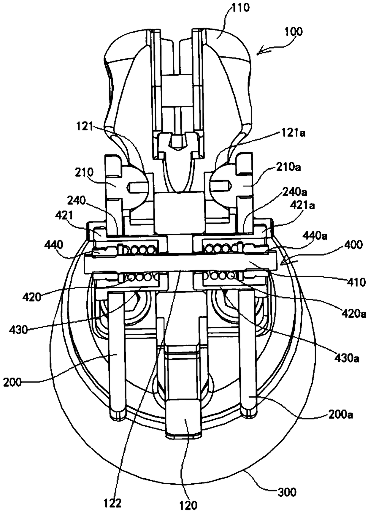
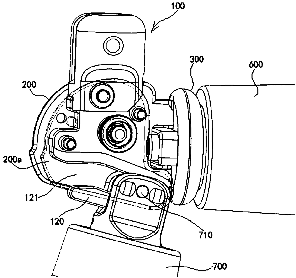
[0015] see figure 1 with figure 2 , an adaptive movable conductive connection mechanism shown in the figure, including a static contact seat 100, two conductive clips 200, 200a, a supporting insulator 300, a clamping spring assembly 400 and two positioning pins 500, 510.

[0016] The static contact seat 100 includes a conductive seat 110 and a guide seat 120, the conductive seat 120 is fixed on the guide seat 120 by fasteners, and the guide seat 120 is installed on the support insulator 300; inner tapered holes are respectively provided on both sides of the conductive seat 120 121, 121a, the inner tapered holes 121, 121a are V-shaped in radial section.

[0017] A mounting hole 122 and two positioning pin mounting holes 123 , 124 are provided on the guide seat 120 for passing through the clamping spring assembly 400 and the two positioning pins 500 , 510 .

[0018] A positioning pin 500 , 510 is installed in each of the two positioning pin mounting holes 123 , 124 .

[0019...


PUM


Abstract

The invention discloses an adaptive movable conductive connecting mechanism comprising static contact seats, two conductive clamp pieces, and a clamp spring assembly; the static contact seats comprise a conductive seat and a guide seat; the conductive seat is fixed on the guide seat; the guide seat is arranged on a support insulator; two sides of the conductive seat are respectively provided with an inner taper hole; the two conductive clamp pieces are respectively arranged on two sides of the static contact seat; the upper portions of the two conductive clamp pieces are respectively shafted by a conductive hemisphere; the two conductive hemispheres are respectively embedded into the inner taper holes for conductive contacts; the clamp spring assembly is arranged in a mount hole of the guide seat; two ends of the clamp spring assembly extend outside the two sides of the guide seat, and are respectively connected with the two conductive clamp pieces. The adaptive movable conductive connecting mechanism can solve the electric connection problems of the movable and static contacts of a rotary type knife switch.

Description

technical field [0001] The invention relates to the field of electric equipment, in particular to an adaptive movable conductive connection mechanism on a knife switch in a switch cabinet. Background technique [0002] The knife switch has the characteristics of simple structure and reliable operation. It is widely used in complete switchgear and independent switching elements in the power switch industry. In the current knife switch, in order to ensure a good conductive contact between the moving knife and the static contact, according to the size of the current flow capacity, multi-contacts or multi-contact fingers are usually used, but due to the small contact area of ​​a single contact Small, limited flow capacity, and in the structure of multiple contacts (contact fingers), affected by the processing and installation accuracy of parts, usually only part of the contact fingers can be reliably contacted, which affects the overall flow capacity of the switch. Contents o...

Claims


Application Information

Patent Timeline
Patent Type & Authority Patents(China)
IPC IPC(8): H01H21/14H01H1/16H01H21/54
CPCH01H1/16H01H21/14H01H21/54
Inventor 钱立骁陆逸王陆一
Owner 希捷爱斯(上海)电气有限公司
Learn More