Connection structure between moving spring part and base of magnetic latching relay

A technology of magnetic latching relays and moving springs, applied in electromagnetic relays, electromagnetic relay details, relays, etc., can solve the problems of low consistency and large variation in positioning methods, and achieve the goal of improving positioning accuracy and avoiding accumulated tolerances. Effect

Active Publication Date: 2019-08-06
XIAMEN HONGFA ELECTRIC POWER CONTROLS
View PDF7 Cites 0 Cited by
  • Summary
  • Abstract
  • Description
  • Claims
  • Application Information

AI Technical Summary

Problems solved by technology

[0003] The moving spring part of the magnetic latching relay in the prior art usually includes a moving reed and a moving spring lead-out piece. Usually the moving reed is composed of a plurality of reeds stacked together, and one end of the moving reed is fixed to one end of the moving spring lead-out piece. The other end of the moving reed is connected to the moving contact, and the other end of the moving spring lead-out piece is exposed outside the base as a lead-out part; at the fixed position between one end of the moving reed and one end of the moving spring lead-out piece, usually in the moving spring There is a through hole on the piece, and there is a convex bud on the moving spring lead-out piece. After the through hole of the moving reed is matched with the convex bud of the moving spring leading piece, the two are fixed together by riveting; the moving spring part is installed on the During base, be to be provided with slot on base, move spring part is pressed in the slot of base, make move spring part and base be fixed together, the move spring part of prior art is to draw out by move spring The material thickness of one end of the sheet plus the material thickness of one end of the multi-leaf reed is used for positioning with the slot of the base. Due to the cumulative tolerance of multiple parts (moving spring lead-out piece, multi-leaf reed), this The variation of positioning methods is large, and the consistency is not high

Method used


Image

  • Connection structure between moving spring part and base of magnetic latching relay
  • Connection structure between moving spring part and base of magnetic latching relay
  • Connection structure between moving spring part and base of magnetic latching relay

Examples


Embodiment

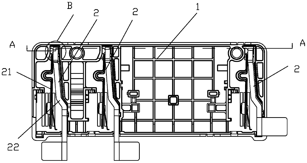
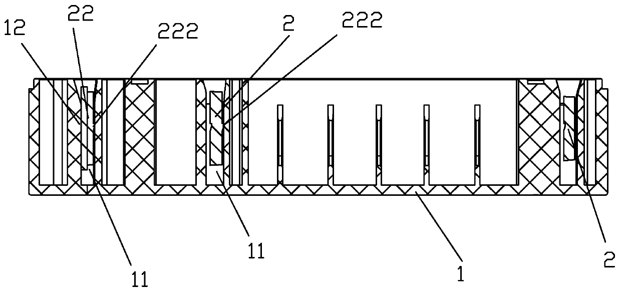
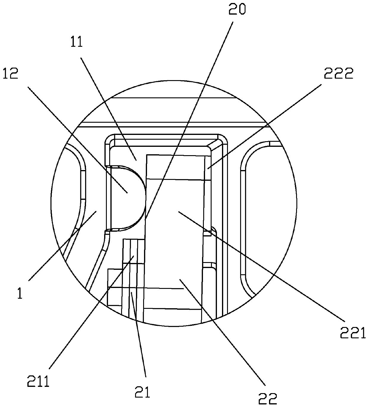
[0024] see Figure 1 to Figure 6 As shown, the connection structure between the moving spring part and the base of a magnetic latching relay of the present invention includes a moving spring part 2 and a base 1; the moving spring part 2 includes a moving reed 21 and a moving spring lead-out piece 22, one end 211 of the moving reed 21 is fixed to one end 221 of the moving spring lead-out piece 22; the base 1 is provided with a slot 11; One side of the thickness of one end 221 of 22 is connected and makes the end of one end 221 of the moving spring lead-out piece longer than the end of one end 211 of the moving reed by a distance 20; in the slot 11 of the base, One side corresponding to the thickness of the moving spring lead-out piece 22 is provided with a rib 12, when the moving spring part 2 is matched with the slot 11 of the base 1, the rib 12 of the slot of the base 1 is used as a positioning reference plane against the The distance between the end 221 of the movable sprin...


PUM


Abstract

The invention discloses a connecting structure between movable spring parts and a base of a magnetic latching relay. The connecting structure comprises the movable spring parts and the base, wherein each movable spring part comprises a movable spring sheet and a movable spring lead-out sheet; one end of the movable spring sheet and one end of the movable spring lead-out sheet are fixed; inserting slots are formed in the base; a thickness plane at one end of the movable spring sheet is connected with a thickness plane at one end of the movable spring lead-out sheet and the end head at one end of the movable spring sheet is longer than the end head at one end of the movable spring lead-out sheet for a certain distance; convex ribs are arranged in the inserting slots, corresponding to the thickness plane of the movable spring lead-out sheet, of the base; and when the movable spring parts are matched with the inserting slots of the base, the convex ribs in the inserting slots of the base are taken as a positioning reference plane to prop against the position, with the distance, at one end of the movable spring lead-out sheet. By virtue of structural improvement, accumulated tolerance caused by multiple parts in the prior art can be avoided, thereby improving the positioning precision of the movable spring lead-out sheets.

Description

technical field [0001] The invention relates to a magnetic latching relay, in particular to a connection structure between the moving spring part and the base of the magnetic latching relay. Background technique [0002] Magnetic latching relays usually consist of a magnetic circuit system, a contact system, a push mechanism and a base. The magnetic circuit system generally consists of two basically symmetrical magnetic circuits, including stationary magnetizer parts, movable magnetizer parts and coils, the contact system includes a moving spring part and a static spring part, and the push mechanism mainly includes a push card. The relay coil passes the positive pulse voltage, the magnetic circuit system works, pushes the card to push the moving spring part, makes the moving contact of the moving spring part contact the static contact of the static spring part, the relay operates, the coil passes the reverse pulse voltage, and the magnetic The circuit system works, push the...

Claims


Application Information

Patent Timeline
Patent Type & Authority Patents(China)
IPC IPC(8): H01H50/04H01H50/68H01H51/01
CPCH01H50/042H01H50/68H01H51/01
Inventor 钟叔明殷剑锋
Owner XIAMEN HONGFA ELECTRIC POWER CONTROLS
Why Eureka
Try Eureka