Supercharge Your Innovation With Domain-Expert AI Agents!

Reactive power compensation method of power network

A technology of power grid and power grid system, applied in the field of data grid control, can solve the problems of poor stability, poor convergence, roughness, etc.

Inactive Publication Date: 2017-05-10
TSINGHUA UNIV +3
View PDF3 Cites 5 Cited by
  • Summary
  • Abstract
  • Description
  • Claims
  • Application Information

AI Technical Summary

Problems solved by technology

These two methods more or less have the characteristics of large amount of calculation, poor convergence and poor stability.
Therefore, in practical applications, the compensation mainly depends on the experience of the dispatcher, such as centralized compensation (unified compensation of the entire system) and decentralized compensation (local compensation next to the power load). The disadvantage is that it is relatively rough and cannot obtain optimal results.

Method used


Image

  • Reactive power compensation method of power network
  • Reactive power compensation method of power network
  • Reactive power compensation method of power network

Examples


Embodiment Construction

[0015] The specific implementation manners of the present invention will be further described in detail below in conjunction with the accompanying drawings and embodiments. The following examples are used to illustrate the present invention, but are not intended to limit the scope of the present invention.

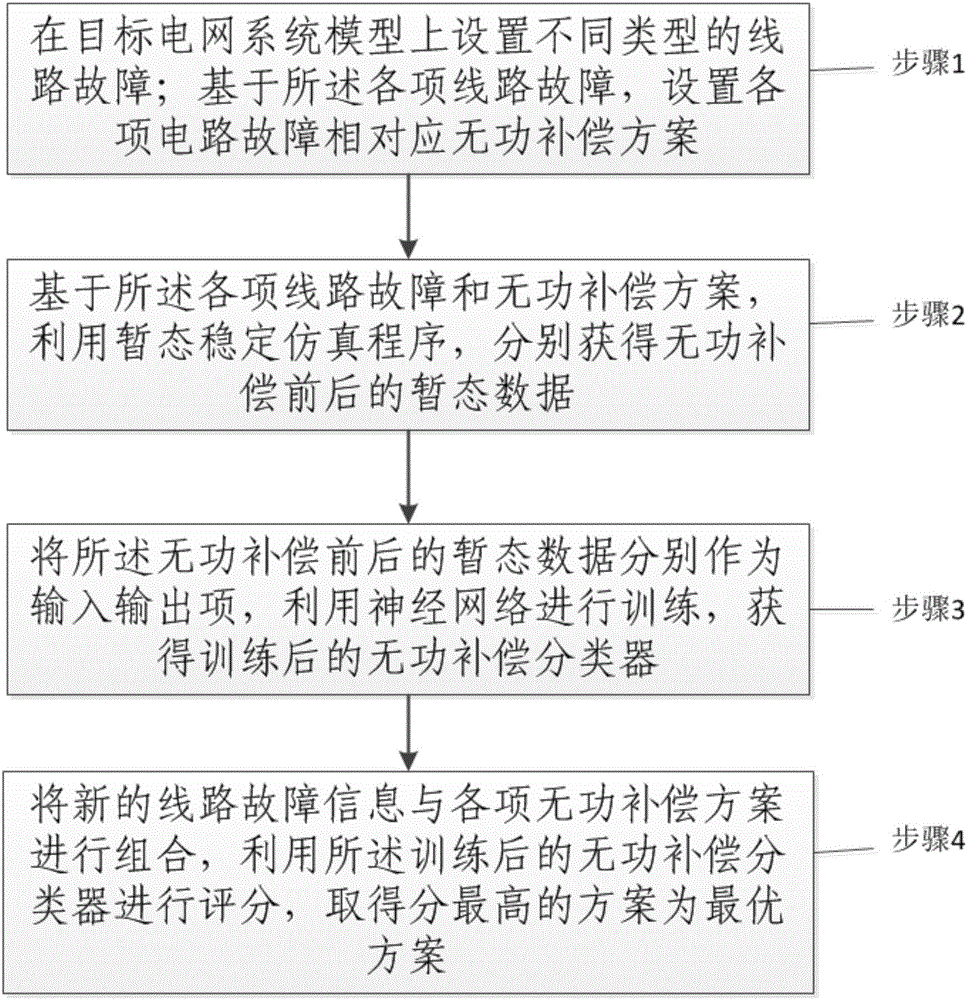
[0016] figure 1 In the figure, according to a specific implementation of the present invention, a schematic flowchart of an overall flow of a reactive power compensation method for a power grid is shown. Generally speaking, it includes: step 1, setting different types of line faults on the target power grid system model; based on the various line faults, setting the reactive power compensation scheme corresponding to each circuit fault; For the line fault and reactive power compensation scheme, use the transient stability simulation program to obtain the transient data before and after reactive power compensation respectively; step 3, use the transient data before and aft...


PUM


Abstract

The invention provides a reactive power compensation method of a power network. The method comprises the steps of setting different types of line faults on an objective power network system model; setting corresponding reactive power compensation schemes for various line faults on the basis of the line faults; obtaining transient data before and after reactive power compensation separately by using a transient stability simulation program on the basis of the line faults and the reactive power compensation schemes; taking the transient data before and after reactive power compensation as input and output items separately, carrying out training by using a neural network and obtaining a trained reactive power compensation classifier; and combining new line fault information with various reactive power compensation schemes, carrying out grading by using the trained reactive power compensation classifier and obtaining the scheme with the highest score as an optimal scheme. The beneficial effects of accurately and quantitatively determining reactive power compensation places and total amount, reducing human intervention and greatly improving the stability and the security of the power network are achieved.

Description

technical field [0001] The present invention relates to the technical field of data grid control, and more specifically, to a reactive power compensation method for a grid. Background technique [0002] At present, the power grid is regarded as the most complex artificial system today, and people still cannot fully understand and master the operation rules of the power system. The traditional simulation modeling analysis makes a lot of assumptions and simplifications on the power system, which makes the simulated results deviate from the real system. With the development of distributed computing and machine learning, big data analysis has become an important means of understanding complex systems. Big data analysis regards the real system as a black box, and directly performs fitting and correlation analysis on the input and output. Compared with the traditional simulation analysis that needs to solve a large number of differential equations, the data-based machine learnin...

Claims


Application Information

Patent Timeline
IPC IPC(8): H02J3/18
CPCH02J3/1871Y02E40/30
Inventor 曹军威赵兵兵邱金辉杨飞贾松江陶冶刘君周培忠
Owner TSINGHUA UNIV
Features
  • R&D
  • Intellectual Property
  • Life Sciences
  • Materials
  • Tech Scout
  • Unparalleled Data Quality
  • Higher Quality Content
  • 60% Fewer Hallucinations
Learn More