Supercharge Your Innovation With Domain-Expert AI Agents!

Charging circuits and terminal equipment

A charging circuit and power pin technology, applied in the field of electronics, can solve the problems of slow charging speed, small charging current, slow charging, etc., and achieve the effect of improving charging speed, solving slow charging speed and improving safety.

Active Publication Date: 2020-05-12
QIKU INTERNET TECH SHENZHEN CO LTD
View PDF5 Cites 0 Cited by
  • Summary
  • Abstract
  • Description
  • Claims
  • Application Information

AI Technical Summary

Problems solved by technology

In other words, even if the OTG host has a strong load capacity, it cannot provide a larger charging current.
However, in the case that the current battery capacity generally exceeds 3000mAh, charging with a current specification of 500mA is extremely slow, and basically has no practical value.
[0011] To sum up, when the existing terminal equipment is charged externally, the charging current is small and the charging speed is extremely slow

Method used


Image

  • Charging circuits and terminal equipment
  • Charging circuits and terminal equipment
  • Charging circuits and terminal equipment

Examples


Embodiment 1

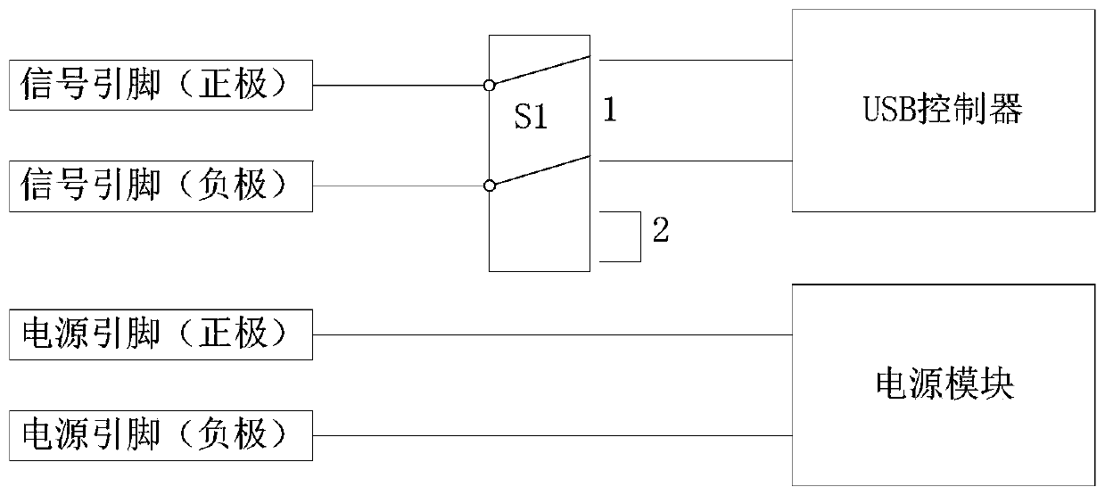
[0037] refer to figure 2 , the charging circuit according to the first embodiment of the present invention is proposed, the charging circuit includes two signal pins, two power pins, a USB controller, a power module and a first switch S1. The two power pins are electrically connected to the power module, and the two signal pins are switched between two states of being short-circuited to each other and being electrically connected to the USB controller through the first switch S1.

[0038] In the embodiment of the present invention, the two signal pins are a pair of differential signal pins of the USB interface, including a positive pin (D+) and a negative pin (D-). In other embodiments, it may also be other types of signal pins, which are not limited here.

[0039] In the embodiment of the present invention, the two power supply pins are the positive pin (VBUS) and the negative (ground) pin (GND) of the USB interface. In other embodiments, other types of power supply pins m...

Embodiment 2

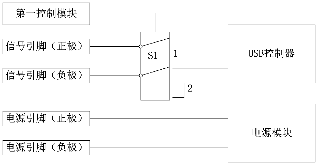
[0045] refer to image 3 , propose the charging circuit of the second embodiment of the present invention, this embodiment adds a first control module on the basis of the first embodiment, the first control module is electrically connected with the first switch S1, and is used to control the first switch Switching operation of S1. Optionally, the first control module may also be integrated with other electronic components of the terminal device.

[0046] In the first embodiment, the user needs to switch the first switch S1 manually. In this embodiment, the first control module automatically switches the first switch S1 when receiving a switching instruction or determining that the switching condition is satisfied. Thereby improving the intelligence level and enhancing the user experience.

Embodiment 3

[0048] refer to Figure 4 , the charging circuit of the third embodiment of the present invention is proposed. This embodiment adds a second switch S2 on the basis of the first embodiment. At least one of the two power supply pins is electrically connected to the power supply through the second switch S2. module.

[0049] In the embodiment of the present invention, the second switch S2 is connected in series between the positive pin of the power pin (such as VBUS) and the power module, that is, the positive pin of the power pin is electrically connected to the power module through the second switch S2. Optionally, the negative pin of the power supply pin may be electrically connected to the power supply module through the second switch S2, or both power supply pins are electrically connected to the power supply module through the second switch S2.

[0050] In the aforementioned first and second embodiments, when the USB data cable is plugged in, when the USB interface type ne...


PUM


Abstract

The invention discloses a charging circuit and terminal equipment. The charging circuit comprises two signal pins, two power supply pins, a USB controller and a power supply module; and the two power supply pins are connected with the power supply module electrically. In addition, the charging circuit also includes a first switch; and the two signal pins are switched between a mutual short circuit state and a state of electrical connection with the USB controller by the first switch. According to the charging circuit, because the first switch is arranged between the signal pins and the USB controller and thus the two signal pins are switched between the mutual short circuit state and the state of electrical connection with the USB controller by the first switch, switching of USB interfaces between an SDP type and a DCP type can be realized; and when switching to a DCP type is realized, external charging is realized by using heavy currents, so that the charging speed can increase. Therefore, a technical problem of slow charging speed during external charging of terminal equipment can be solved.

Description

technical field [0001] The invention relates to the field of electronic technology, in particular to a charging circuit and terminal equipment. Background technique [0002] Universal Serial Bus (USB) powering portable devices has become a standard application along with its serial communication function. Today, USB power delivery has been extended to battery charging, wall adapters and other forms of power applications. A notable effect brought by the popularization of applications is that the charging and power supply of portable devices can be interchanged with plugs and adapters. As a result, current solutions allow multiple power sources to be used for charging, as opposed to past architectures that used dedicated adapters for each device. [0003] Taking USB2.0 as an example, there are 5 pins (PIN) in the USB2.0mini interface, including: [0004] A pair of power pins: VBUS / GND [0005] A pair of signal pins: D+ / D- [0006] One master-slave identification pin: UID ...

Claims


Application Information

Patent Timeline
Patent Type & Authority Patents(China)
IPC IPC(8): H02J7/00
CPCH02J7/00
Inventor 张哲
Owner QIKU INTERNET TECH SHENZHEN CO LTD
Features
  • R&D
  • Intellectual Property
  • Life Sciences
  • Materials
  • Tech Scout
  • Unparalleled Data Quality
  • Higher Quality Content
  • 60% Fewer Hallucinations
Learn More