Charging stations for electric vehicles

a charging station and electric vehicle technology, applied in hybrid vehicles, rail devices, cell components, etc., can solve the problems of electric bus lines being suspended, electric vehicles are limited by current infrastructure, and the entire electric bus line is expensive to install and maintain, so as to reduce the impedance

Active Publication Date: 2010-02-18
PROTERRA OPERATING CO INC
View PDF17 Cites 92 Cited by
  • Summary
  • Abstract
  • Description
  • Claims
  • Application Information

AI Technical Summary

Benefits of technology

[0010]A system for charging a vehicle may be provided in accordance with another embodiment of the invention. The system may include a charging station with two or more collector braces and a vehicle with two or more contact plates. The collector braces may be configured to receive contact plates on top of the vehicle such that the contact plates slide between electrically conductive surfaces after being guided by guiding strips. The contact plates may be squeezed between the guiding strips to ensure good electrical contact. Furthermore, the electrically conductive surfaces may have a surface area that contacts the contact plates, which may provide an area of electrical contact. Such features may decrease impedance at the charging interface between the charging station and vehicle, which may aid in fast charging. The charging station may also include a spacing bar to keep the collector braces at a desired distance apart from one another, which may match the distance between the contact plates of the vehicle. The charging station may also include a flexible connection for a connecting structure that connects the charging mount and collector braces, which may enable the connecting structure and contact assemblies to move laterally with respect to the direction of vehicle travel. This may provide tolerance for vehicle dimensions, drive path, or other vehicle attributes.

Problems solved by technology

Electric vehicles are limited by current infrastructure for transferring power to the electric vehicles.
While systems for maintaining a permanent electrical connection along a route taken by an electric vehicle can be used to transfer power to the electric vehicle, these systems are an eyesore, are unpopular, are costly to install and maintain, and can be unsafe.
These systems often require the entire electric bus line to be suspended for periods of time while cities perform routing building maintenance or construction.
Some of these systems do not enable an electrical vehicle to run independent of a railing or overhead line.
Also, some of these systems are not adaptable to different vehicles with different characteristics.
Furthermore, these systems may take a significant amount of time or effort to charge.

Method used


Image

  • Charging stations for electric vehicles
  • Charging stations for electric vehicles
  • Charging stations for electric vehicles

Examples


Embodiment Construction

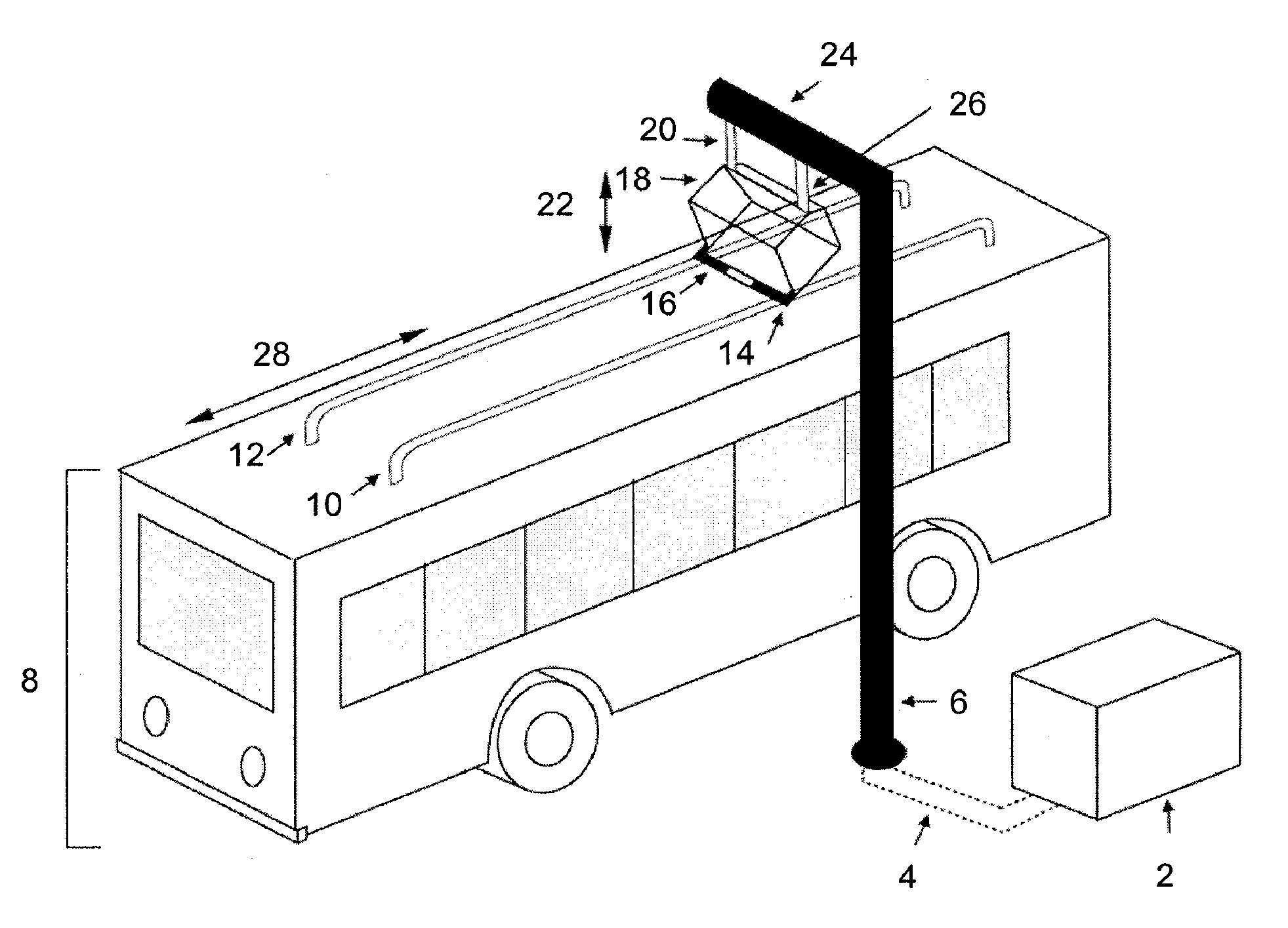
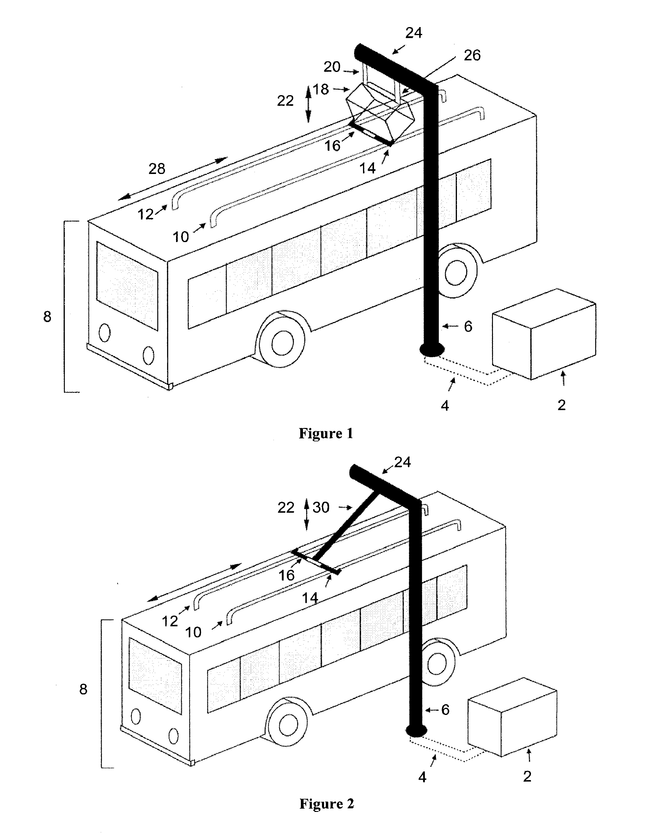
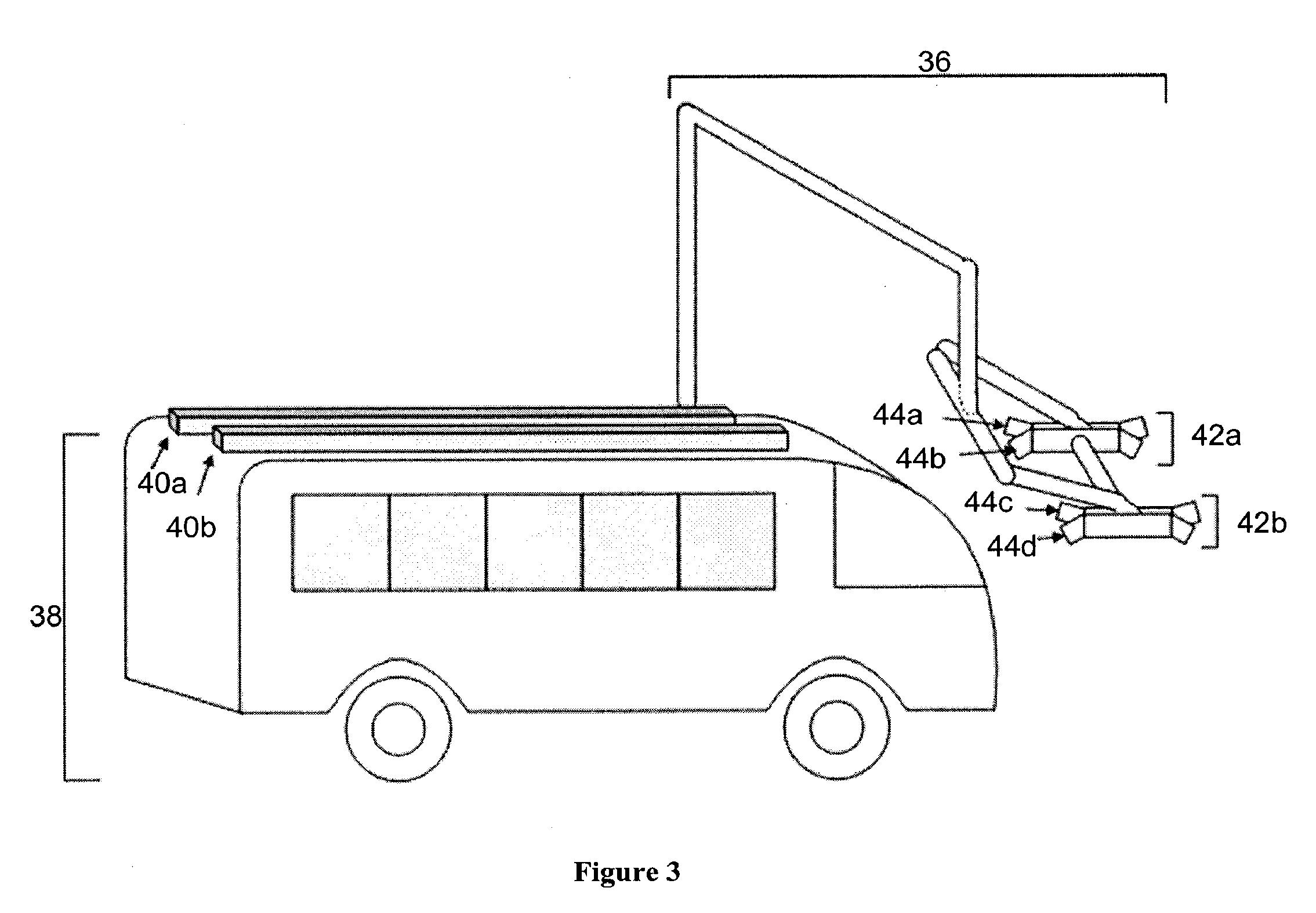
[0026]The invention provides for systems and methods for charging an electric vehicle. One aspect of the invention provides for a charging station. The charging station can be used to transfer power to an electrically powered vehicle. The charging station may be used to transfer power to any electric vehicle, hybrid electric vehicle, or any other vehicle that may include a propulsion power source, such as a battery, ultracapacitor, or any other energy storage system. In some embodiments, an electrically powered vehicle may be a heavy duty vehicle, such as a bus or truck.

[0027]For example, electrical vehicles powered by the system may include a transit bus, a school bus, a delivery van, a shuttle bus, a tractor trailer, a class 5 truck (weighing 16,001-19,500 lbs., two-axle, six-tire single unit), a class 6 truck (weighing 19,501-26,000 lbs., three-axle single unit), a class 7 truck (weighing 26,001-33,000 lbs., four or more axle -single unit), a class 8 truck (weighing 33,000 lbs. a...


PUM

PropertyMeasurementUnit
surface areaaaaaaaaaaa
voltageaaaaaaaaaa
voltageaaaaaaaaaa

Abstract

The invention relates to systems and methods for charging a vehicle. A vehicle and charging station can be designed such that an electric or hybrid vehicle can operate in a fashion similar to a conventional vehicle by being opportunity charged throughout a known route.

Description

CROSS-REFERENCE[0001]This application claims the benefit of U.S. Provisional Application No. 61 / 077,452, filed Jul. 1, 2008, and U.S. Provisional No. 61 / 174,926, filed May 1, 2009, which applications are incorporated herein by reference in their entirety.STATEMENT AS TO FEDERALLY SPONSORED RESEARCH[0002]This invention was made with the support of the United States government under the National Fuel Cell Bus program, Contract number ______ by the Federal Transit Administration (FTA).BACKGROUND OF THE INVENTION[0003]Electric vehicles are limited by current infrastructure for transferring power to the electric vehicles. Some electric vehicles, such as electric trains and light rail cars, are permanently connected to a power source through hardware in the railing or through overhead lines. Other electric vehicles, such as electric cars, are charged by plugging in the electric vehicle at a charging station.[0004]While systems for maintaining a permanent electrical connection along a rout...

Claims


Application Information

Patent Timeline
Patent Type & Authority Applications(United States)
IPC IPC(8): H02J7/00H01M2/30
CPCB60L5/42Y02T10/7072B60L11/1837B60L11/185B60L2200/18Y02T10/7005Y02T10/7088Y02T90/121Y02T90/128Y02T90/14B60L11/1825B60L2200/26B60L11/1824B60L11/1827B60L5/005H02J7/0021B60L11/1816B60L53/14B60L53/30B60L53/31B60L53/35B60L53/32B60L53/11Y02T90/12Y02T10/70H02J7/00H02J7/007B60M7/003H02J7/0042
Inventor HILL, DALEWALKER, MICHAELGOLDMAN, JOSHUAHORTH, JOHN
Owner PROTERRA OPERATING CO INC
Why Eureka
Try Eureka