Linkage type solar photovoltaic tracking system with cam driving apparatus
A solar photovoltaic and driving device technology, applied in the direction of photovoltaic power generation, photovoltaic modules, photovoltaic module support structures, etc., can solve the problems of unfavorable photovoltaic power generation development, uneven force on photovoltaic modules, low transmission accuracy, etc., and achieve low cost, Uniform force, simple and compact drive
- Summary
- Abstract
- Description
- Claims
- Application Information
AI Technical Summary
Problems solved by technology
Method used
Image

Examples
Embodiment 1
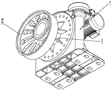
[0020] Such as figure 1 As shown, this embodiment is a cam driving device, including a reducer 1 and a driving cam 2 connected to the output shaft 3 of the reducer, and the reducer adopts a three-stage integrated rotary reducer. The connection position between the drive cam and the output shaft of the reducer is located at a position deviated from the center of the drive cam circle, and the drive cam rotates around the connection position with the output shaft of the reducer under the drive of the output shaft of the reducer. Since this position is located at a position where the driving cam deviates from the center of the circle, during the rotation of the driving cam, the distance between the rotation axis and the left and right edges of the cam is constantly changing, so that the circular motion of the cam can be transformed conveniently. It is the linear motion of the transmission device that cooperates with it. It is especially suitable for large thrust and low speed occ...
Embodiment 2
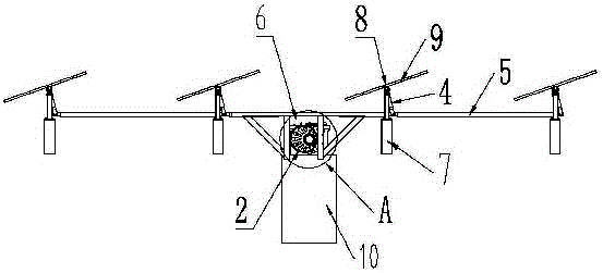
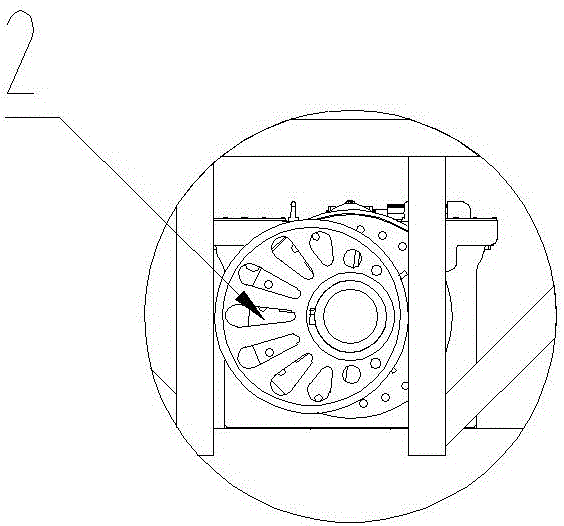
[0022] Such as Figure 2-4 As shown, this embodiment is a cam driving device, including a cam driving device and a transmission device. The cam driving device includes a reducer 1 and a drive cam 2 connected to the output shaft 3 of the reducer. The reducer adopts a three-stage integrated Rotary reducer. The connecting position of the driving cam and the output shaft of the reducer is located at a position deviated from the center of the driving cam circle. The transmission device includes a drive cross-link 4 and a plurality of drive push rods 5, and a plurality of drive push rods are connected to the drive cross-link. A U-shaped groove 6 is arranged on the driving cross-link, and the U-shaped groove is preferably arranged near the center of the drive cross-link. The driving cam is arranged in the U-shaped groove and can rotate in the U-shaped groove. The driving cam rotates in the U-shaped groove to drive the horizontal connecting rod to move left and right. Driven by th...
Embodiment 3
[0024] Such as Figure 5 As shown, the difference between this embodiment and Embodiment 2 is that it includes a plurality of driving cross-links, and the driving cross-links are arranged between two adjacent driving push rods and are hinged to the two driving push rods. The rotary motion of the previous drive push rod is transmitted to the next drive push rod through the drive cross link connected therewith, and then drives the drive push rod of the whole device to maintain consistent motion. The U-shaped groove is arranged on one of the driving cross-links, preferably at an approximately middle position of the cam drive device, that is, on the cross-link in the middle position among the plurality of cross-links in the device, and is further preferably located at this The middle position of the transverse link in the middle position.
PUM
 Abstract
Description
Claims
Application Information
 - R&D Engineer
- R&D Manager
- IP Professional
- Industry Leading Data Capabilities
- Powerful AI technology
- Patent DNA Extraction
Browse by: Latest US Patents, China's latest patents, Technical Efficacy Thesaurus, Application Domain, Technology Topic.
© 2024 PatSnap. All rights reserved.Legal|Privacy policy|Modern Slavery Act Transparency Statement|Sitemap