
Shoe capable of increasing air flowing at the bottom of shoe cavity

A gas flow, shoe technology, applied in the direction of soles, uppers, footwear, etc., can solve the problems of air permeability limitation, exhaust gas obstruction, and reducing the safety of foot sole protection.

Inactive Publication Date: 2017-05-17
MAOTAI FUJIAN SOLES CO LTD
View PDF5 Cites 1 Cited by
  • Summary
  • Abstract
  • Description
  • Claims
  • Application Information

AI Technical Summary

Problems solved by technology

The breathability of shoes is the primary choice considered by consumers at present. In the prior art, in order to ensure the breathability of shoes, most shoes adopt a number of holes on the upper of the shoe or use mesh fabric to make the upper. The breathability of the fabric is used to achieve the breathability of the shoes. However, whether it is the holes directly set on the upper of the shoe or the breathable pores of the mesh fabric, during the wearing process, due to the fit of the human foot and the upper, it is easy to cause the holes to be closed. If it is blocked and the exhaust is hindered, the air permeability will be limited and the air permeability will be poor; and the holes are set on the upper, mainly to realize the air circulation on the instep, while the main air circulation on the contact position between the sole of the foot and the shoe is still Poor, and the contact between the sole of the human foot and the shoe is the place where the heat of the foot is the largest, so the air permeability of the shoes in the prior art is not good enough, and the comprehensive ventilation effect in the shoe cavity of the shoe cannot be realized. The holes are easily blocked by external substances such as small stones, and even small branches will cause damage to the soles of the feet, which also reduces the safety of the soles of the feet.

Method used


Image

  • Shoe capable of increasing air flowing at the bottom of shoe cavity
  • Shoe capable of increasing air flowing at the bottom of shoe cavity

Examples


Embodiment Construction

[0011] The present invention will be further described in conjunction with the accompanying drawings and specific embodiments.

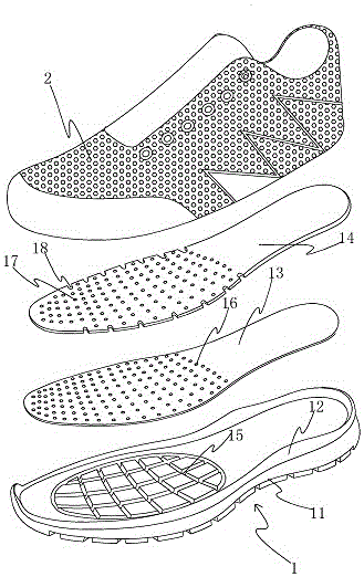
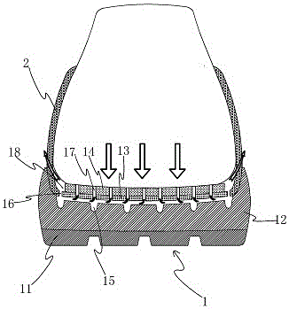
[0012] refer to Figure 1 to Figure 2 , the embodiment of the present invention discloses that a shoe that can increase the gas flow at the bottom of the shoe cavity includes a shoe sole 1 and a shoe upper 2 arranged on the shoe sole. The shoe sole 1 includes a large bottom 11 and a middle Bottom 12, midsole board 13 on the midsole and insole 14 on the midsole board, the upper surface of the forefoot part of the midsole 12 is provided with grid-like exhaust grooves 15, and the grid-like rows The groove width of the air groove 15 is 3.5mm, the groove depth is 3mm, and the grid width formed in the grid-like exhaust groove 15 is 28mm; The first air hole 16; the forefoot of the insole 14 is provided with a plurality of second air holes 17 running through its upper and lower surfaces; the first air hole 16 is connected to the grid-shaped exhaust groove 1...


PUM

PropertyMeasurementUnit
Groove widthaaaaaaaaaa
Groove depthaaaaaaaaaa

Abstract

The invention relates to a shoe and provides a shoe simple in structure, capable of effectively achieving a comprehensive ventilation effect in the shoe, excellent in breathable property, high in safety protectivity and capable of increasing air flowing at the bottom of a shoe cavity. The shoe comprises a shoe sole and a shoe vamp arranged on the shoe sole, wherein the shoe sole comprises a large sole, a middle sole arranged on the large sole, a middle base plate arranged on the middle sole and a shoe pad arranged on the middle base plate, the upper surface of the middle sole is provided with grid-shaped exhausting grooves, the middle sole plate is provided with multiple first breathable holes penetrating through the upper surface and the lower surface, the shoe pad is provided with multiple second breathable holes penetrating through the upper surface and the lower surface, the first breathable holes are communicated to the grid-shaped exhausting grooves, and the second breathable holes are communicated with the first breathable holes. The side edge of the shoe pad is provided with multiple exhausting gaps, the exhausting gaps are sequentially arranged in the length direction of the shoe pad, and the exhausting gaps are communicated with the first breathable holes located in the side edge of the middle sole plate, and the shoe vamp is provided with breathable net holes.

Description

technical field [0001] The invention relates to a shoe, in particular to a shoe capable of increasing gas flow at the bottom of a shoe cavity. Background technique [0002] Shoes, as people's daily necessities, undertake functions such as keeping warm, protecting, and looking beautiful. The breathability of shoes is the primary choice considered by consumers at present. In the prior art, in order to ensure the breathability of shoes, most shoes adopt a number of holes on the upper of the shoe or use mesh fabric to make the upper. The breathability of the fabric is used to achieve the breathability of the shoes. However, whether it is the holes directly set on the upper of the shoe or the breathable pores of the mesh fabric, during the wearing process, due to the fit of the human foot and the upper, it is easy to cause the holes to be closed. If it is blocked and the exhaust is hindered, the air permeability will be limited and the air permeability will be poor; and the hole...

Claims


Application Information

Patent Timeline
IPC IPC(8): A43B7/06A43B13/16A43B17/08A43B23/02
CPCA43B7/06A43B13/16A43B17/08A43B23/0245
Inventor 庄伟志郑荣大丁思恩郑艺文
Owner MAOTAI FUJIAN SOLES CO LTD
Learn More