Fluid extractor for closed body fluid retention devices

A body fluid and component technology, applied in the field of medical devices, can solve the problems of high material cost and mold cost, complex processing technology, low production efficiency, etc., and achieve the effect of reducing preparation cost, reducing cost and improving efficiency

Active Publication Date: 2017-05-17
WUXI KAISHUN MEDICAL DEVICE MFG CO LTD
View PDF4 Cites 5 Cited by
  • Summary
  • Abstract
  • Description
  • Claims
  • Application Information

AI Technical Summary

Problems solved by technology

Because the liquid taking part has two channels that are not connected, the shapes of the two channels are different; and the different sections of each channel are also different; secondly, the integrated structure makes the annular side wall and the ring side wall for collecting liquid of the liquid taking part The same material is used for the diversion liquid and gas parts, so the processing technology is complicated, the cost of materials and molds is large, and the production efficiency is low
[0004] In addition, when the liquid taking part pours out the excess liquid in the liquid taking part, the liquid in the test tube matched with the liquid taking part is easy to pour out from the exhaust channel or the liquid guide channel

Method used


Image

  • Fluid extractor for closed body fluid retention devices
  • Fluid extractor for closed body fluid retention devices
  • Fluid extractor for closed body fluid retention devices

Examples


Embodiment 1

[0078] Embodiment 1: below in conjunction with attached Figure 1 to Figure 4 The present invention is further described.

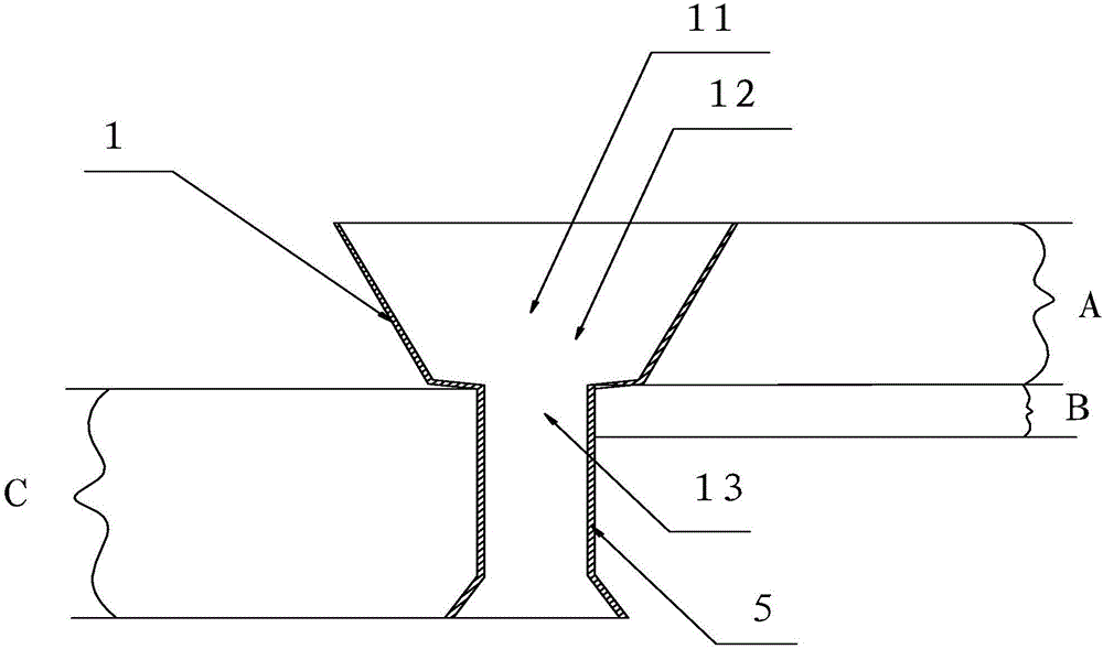
[0079] A liquid taking part for a closed body fluid indwelling device, comprising an annular side wall 1 and a channel assembly 2 .

[0080] The annular side wall 1 includes part A for gathering liquid, part B and part C for connecting, and part C is used to prevent external liquid from contaminating the test tube matched with the liquid-taking part. Part C and part B may be independent, and part C may also include part B, that is, part B is a part of part C.

[0081] The annular side wall 1 encloses and forms a channel 11 , and the channel component 2 is vertically arranged in the channel 11 , and sealingly fits with the lower part 13 of the channel. That is, the channel assembly 2 is sealingly engaged with the portion B of the annular side wall 1 .

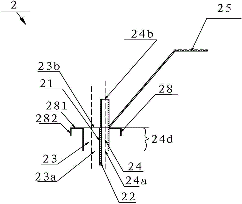
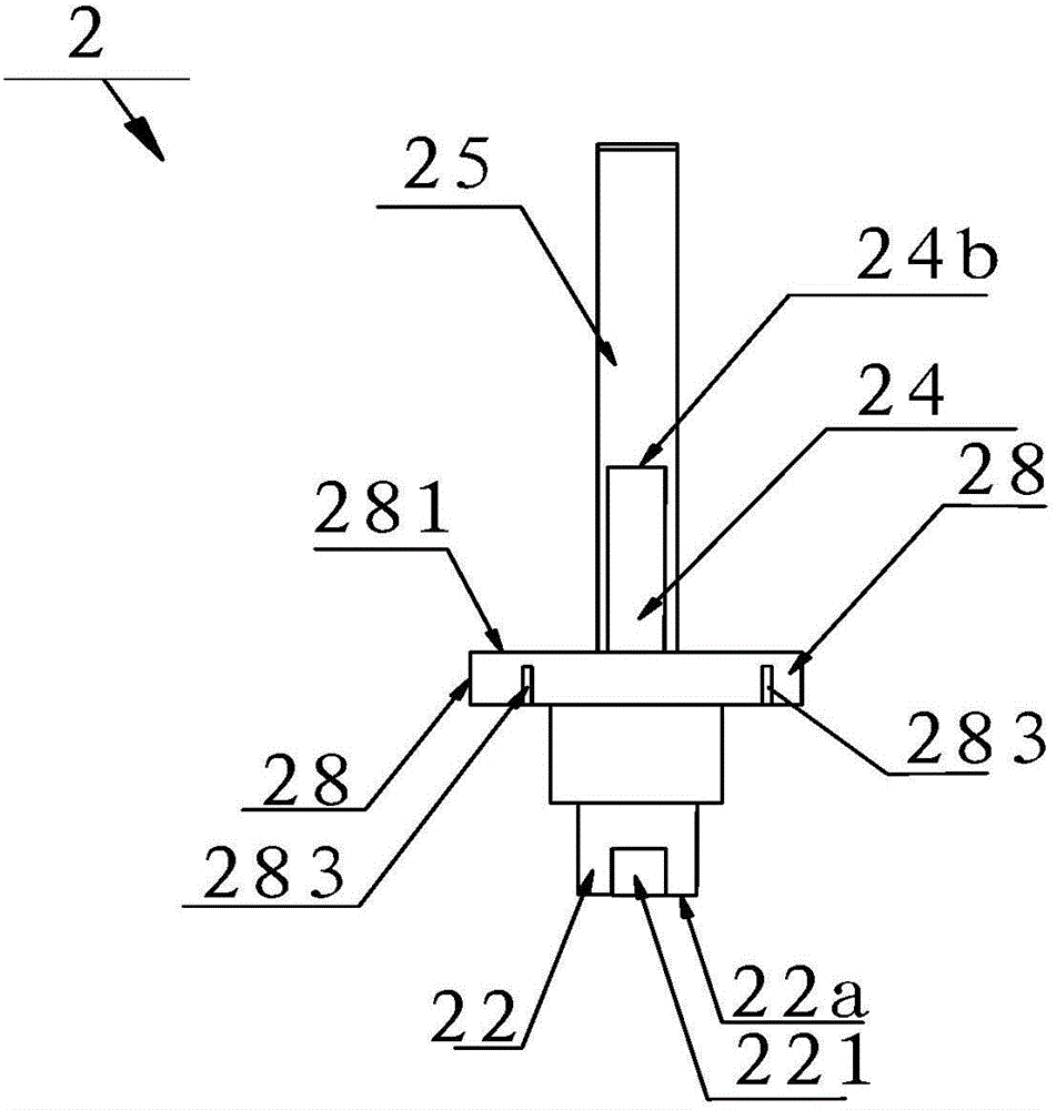
[0082] The channel assembly 2 is provided with an axial through hole A 24 for exhaust and a through h...

Embodiment 2

[0090] Embodiment 2: below in conjunction with attached Figure 5 , Figure 8 , Figure 15 , Figure 16 The present invention is further described.

[0091] A liquid taking part for a closed body fluid indwelling device, comprising an annular side wall 1 and a channel assembly 2 .

[0092] The annular side wall 1 includes part A for gathering liquid, part B for connecting and part C for preventing external liquid from contaminating the test tube matched with the liquid-taking part. Parts A, B and C are integrated. The annular side wall 1 is provided with an inward bend 15, and the bend 15 is located above the B portion.

[0093] The annular side wall 1 encloses and forms a channel 11 . The lower outer edge of the channel assembly 2 is circular. The channel component 2 is vertically arranged in the channel 11 , the channel component 2 is plug-fitted with the annular side wall 1 , and the annular side wall 1 is sealingly fitted with the lower part 13 of the channel. That...

Embodiment 3

[0102] Embodiment 3: below in conjunction with attached figure 1 , Figure 7 , Figure 17 The present invention is described further.

[0103] A liquid taking part for a closed body fluid indwelling device, comprising an annular side wall 1 and a channel assembly 2 .

[0104] The annular side wall 1 includes part A for gathering liquid, part B and part C for connecting, and part C is used to prevent external liquid from contaminating the test tube matched with the liquid-taking part. Part C and part B may be independent, and part C may also include part B, that is, part B is a part of part C.

[0105] The annular side wall 1 encloses and forms a channel 11 , and the channel component 2 is vertically arranged in the channel 11 , and sealingly fits with the lower part 13 of the channel. That is, the channel assembly 2 is sealingly engaged with the portion B of the annular side wall 1 .

[0106] The channel assembly 2 is provided with an axial through hole A 24 for exhaust a...


PUM


Abstract

The invention relates to the field of medical appliances, particularly a collecting device for collecting the body fluid. The fluid extractor for closed body fluid retention devices comprises an annular side wall and a channel assembly, wherein the annular side wall forms a channel; the channel assembly is arranged in the channel and positioned on the lower part of the channel; the channel assembly and annular side wall form a split fit; the channel assembly is provided with a through hole; the upper part of the channel is used for collecting the fluid; and the lower part of the channel is matched and connected with the channel assembly. The fluid extractor is capable of lowering the cost and enhancing the production efficiency; and when the excess fluid is poured out of the fluid extractor, the fluid in the test tube can be prevented from being poured out from the diversion channel or exhaust channel.

Description

technical field [0001] The invention relates to the field of medical devices, in particular to a collection device for collecting body fluids. Background technique [0002] The liquid taking part for the airtight body fluid indweller in the prior art only has a diversion channel, and no exhaust channel is provided. When in use, the liquid-taking part is tightly matched with the test tube, and the liquid-taking part collects the liquid and then transfers the liquid to the test tube. However, at the joint between the liquid-taking part and the container, liquid retention often occurs. Even if the liquid taking part is provided with an exhaust channel, during the liquid guiding process, the liquid will still flow to the exhaust port to block the exhaust port, resulting in liquid retention. [0003] Most of the liquid taking parts for the airtight body fluid indwelling device in the prior art are of an integrated structure. Because the liquid taking part has two channels tha...

Claims


Application Information

Patent Timeline
Patent Type & Authority Applications(China)
IPC IPC(8): B01L3/00
CPCB01L3/56
Inventor 不公告发明人
Owner WUXI KAISHUN MEDICAL DEVICE MFG CO LTD
Why Eureka
Try Eureka