
Depressing and balancing device for steel section straightener

A technology of a balancing device and a pressing device, which is applied in the field of metallurgical equipment, can solve the problems of large bouncing of steel straightening machines, poor straightening effect of profiles, and difficulty in automation, and achieves the effects of improving work efficiency, facilitating maintenance, and being easy to automate.

Inactive Publication Date: 2017-05-17
HUATIAN ENG & TECH CORP MCC
View PDF7 Cites 1 Cited by
  • Summary
  • Abstract
  • Description
  • Claims
  • Application Information

AI Technical Summary

Problems solved by technology

The upper stick depressing device of the existing straightening machine includes a lifting mechanism installed on the upper body with a front depressing screw and a rear depressing screw. The front depressing screw and the rear depressing screw expand and contract in the vertical direction, but there is The lower screw and the dart mechanism are threaded, and there is a thread gap, so the section steel straightening machine bounces a lot when the section steel is straightened, the section straightening effect is poor, maintenance is difficult, and it is difficult to realize automation

Method used


Image

  • Depressing and balancing device for steel section straightener
  • Depressing and balancing device for steel section straightener

Examples


Embodiment 1

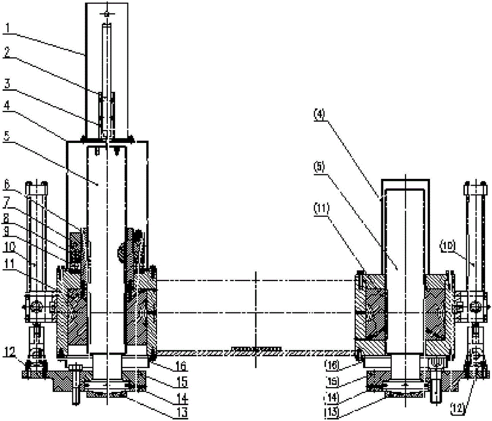
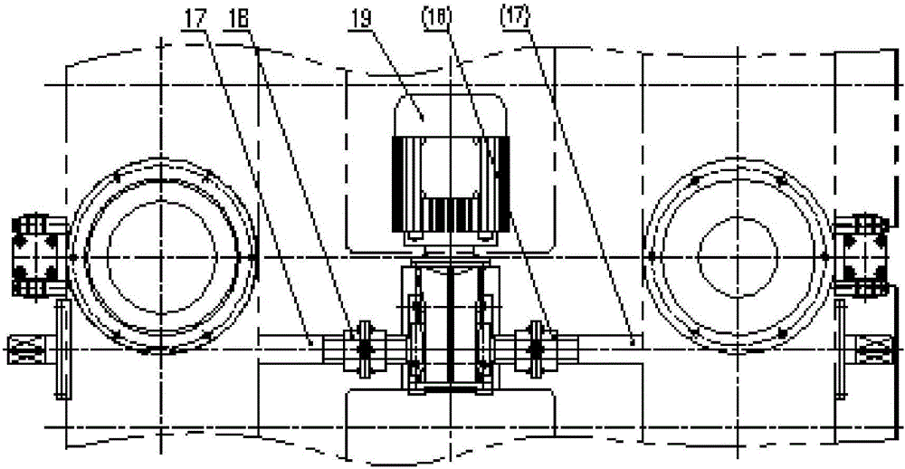
[0017] Such as figure 1 and figure 2 As shown, the profile steel straightening and pressing and balancing device of the present invention includes two sets of pressing devices with pressing screws 5, a driving device for driving the pressing screws 5 up and down, and a driving device for adjusting the pressing screws. the adjustment device;

[0018] Described depressing device comprises worm gear 11, and described worm gear 11 is vertically, rotatably arranged inside the frame box body, and the inner side of described worm gear 11 is threadedly connected with described depressing screw 5;

[0019] The driving device includes a geared motor 19, which is arranged in the middle of two groups of pressing devices; the geared motor is connected with the worm gear to drive the worm gear to rotate;

[0020] The adjusting device includes a hydraulic cylinder, the housing of which is fixed on the outside of the frame box, and the hydraulic cylinder is arranged vertically and parallel...

Embodiment 2

[0023] As a further improvement of the first embodiment, the device further includes a displacement sensor 2, which is arranged on the top of the pressing screw to detect the moving distance of the top of the pressing screw. Specifically, a protective cover 4 is provided on the pressing screw 5, a protective cover 1 is provided on the displacement sensor 2, and the sensor bracket 3 is connected with the protective cover and the protective cover of the left pressing device through bolts or the like. The protective cover is connected with the upper part of the rack box body through bolts.

Embodiment 3

[0025] As a further solution of the above-mentioned embodiments, the geared motor 19 includes a reducer and a motor; the reducer includes an input shaft and two output shafts, the input shaft of the reducer is connected to the output shaft of the motor, and the The two output shafts of the speed reducer are respectively connected with the sleeves in the two sets of pressing devices, and drive the sleeves to rotate.

[0026] Working principle of the present invention is:

[0027] The left and right worm shafts 17 are fixedly installed on the upper part of the frame box, and are connected synchronously through the coupling 18 respectively. Driven by the geared motor, the left and right worm shafts 17 rotate synchronously, driving the left and right worm gear pairs to rotate synchronously, and the left and right worm gear pairs are internally threaded. Down, left and right press the screw to move up or down, and the lower part of the left and right press screw is connected with t...


PUM


Abstract

The invention discloses a depressing and balancing device for a steel section straightener, which is mainly designed to solve the problem of poor steel section straightening effect. The depressing and balancing device comprises two sets of depressing devices with depressing screws, and a driving device used for driving the depressing screws to ascend and descend, and further comprises adjustment devices used for adjusting the depressing screws, wherein each adjustment device comprises a lifting mechanism parallel to the corresponding depressing screw; and each lifting mechanism comprises a fixed part and a movable part moving along the fixed part, the fixed part of each lifting mechanism is fixed on a rack box body, and the movable part of each lifting mechanism is connected with the lower end of the corresponding depressing screw. The vertical position adjustment of an upper rolling system is realized through a gear motor, thread gaps between the depressing screws and nuts are eliminated through hydraulic cylinders, the maintenance is convenient, and the problems of big bounce and poor straightening effect of the steel section straightener during steel section straightening are solved.

Description

technical field [0001] The invention relates to metallurgical equipment, in particular to a pressing and balancing device for a section steel straightening machine. Background technique [0002] Profile straightening is the last process from billet to finished product, and it needs to be straightened according to the requirements of the production process. The upper stick depressing device of the existing straightening machine includes a lifting mechanism installed on the upper body with a front depressing screw and a rear depressing screw. The front depressing screw and the rear depressing screw expand and contract in the vertical direction, but there is The lower screw and the dart mechanism are threaded, and there are thread gaps. Therefore, the section steel straightening machine bounces greatly when the section steel is straightened, the section bar straightening effect is poor, maintenance is difficult, and it is difficult to realize automation. Contents of the inven...

Claims


Application Information

Patent Timeline
IPC IPC(8): B21D3/02
CPCB21D3/02
Inventor 罗华谌喜何家宝周栋孙宝生谷青林朱国民董祖伟陈建
Owner HUATIAN ENG & TECH CORP MCC
Learn More