Eureka AIR delivers breakthrough ideas for toughest innovation challenges, trusted by R&D personnel around the world.

Sealing assembly and sealing equipment

A technology of sealing components and sealing equipment, which is applied in the directions of sealing/isolation, wellbore/well parts, earthwork drilling and production, etc., and can solve the problems of poor sealing performance, small diameter change range, reduced passing performance and sealing performance, etc.

Pending Publication Date: 2017-05-17
BEIJING AOSAIQI PETROLEUM TECH DEV CO LTD
View PDF0 Cites 3 Cited by
  • Summary
  • Abstract
  • Description
  • Claims
  • Application Information

AI Technical Summary

Problems solved by technology

The diameter change range of the sealing assembly of the existing sealing equipment is small and the sealing performance is poor when the diameter is changed, which reduces the passing performance and sealing performance, and reduces the liquid drainage effect

Method used


Image

  • Sealing assembly and sealing equipment
  • Sealing assembly and sealing equipment
  • Sealing assembly and sealing equipment

Examples


Embodiment Construction

[0048] Various exemplary embodiments, features, and aspects of the invention will be described in detail below with reference to the accompanying drawings. The same reference numbers in the figures indicate functionally identical or similar elements. While various aspects of the embodiments are shown in drawings, the drawings are not necessarily drawn to scale unless specifically indicated. The word "exemplary" is used exclusively herein to mean "serving as an example, embodiment, or illustration." Any embodiment described herein as "exemplary" is not necessarily to be construed as superior or better than other embodiments.

[0049] In addition, in order to better illustrate the present invention, numerous specific details are given in the specific embodiments below. It will be understood by those skilled in the art that the present invention may be practiced without certain of the specific details. In some instances, methods, means, and elements well known to those skilled...


PUM


Abstract

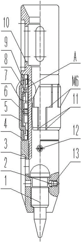
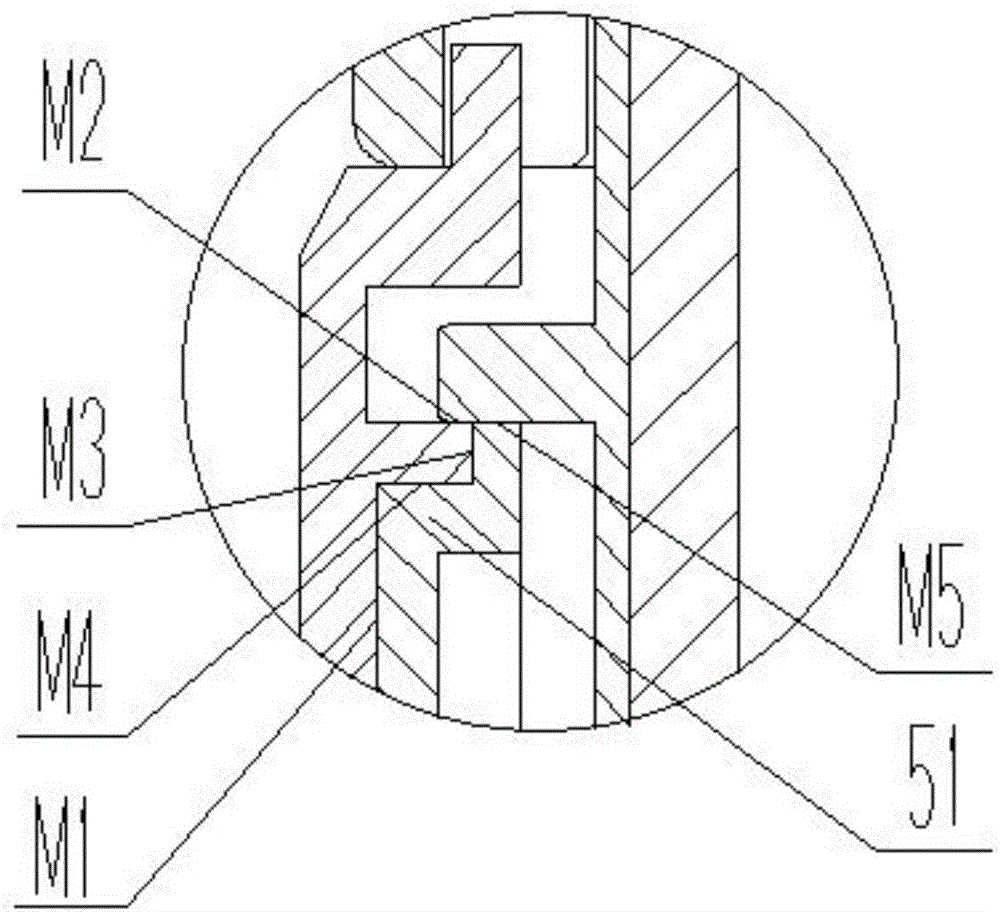
The invention provides a sealing assembly and sealing equipment comprising the sealing assembly. The sealing assembly comprises a sliding sleeve, a sealing sleeve, a first limiting sleeve, a second limiting sleeve and an inner fixed sleeve. The first limiting sleeve and the second limiting sleeve are fixed to the two ends of the inner fixed sleeve correspondingly. The sliding sleeve is formed by splicing at least two sliding branched petals, and the two ends of each sliding branched petal are mounted in the first limiting sleeve and the second limiting sleeve in a radial moving fit mode correspondingly. The outer wall of the sealing sleeve is in seal fit with the inner wall surface of the sliding sleeve. The sealing sleeve is formed by splicing at least two sealing branched petals, and each splicing gap of the sliding branched petals corresponds to one sealing branched petal. An outer boss stretching outwards is arranged on the outer wall of the inner fixed sleeve. An inner boss stretching inwards is arranged on the inner wall of the sliding sleeve. The first side face of the outer boss is in seal fit with the end face of the first side of the inner boss. The sealing performance of the sealing assembly can be guaranteed when the outer diameter of the sealing assembly changes.

Description

technical field [0001] The invention relates to the liquid drainage technology in the fields of oil and gas fields and coalbed methane exploitation, in particular to a sealing assembly, and also relates to a sealing device with the above sealing assembly. Background technique [0002] During the exploitation of low-pressure oil and gas fields and coalbed methane, wellbore fluid accumulation is one of the main problems restricting the stable and high production of oil and gas wells. In order to ensure the normal production of oil and gas wells, it is necessary to discharge the accumulated fluid in the wellbore in time. [0003] The use of sealing equipment is one of the commonly used liquid drainage methods. Its working principle is: the sealing equipment is in the set position underground, and the sealing components of the sealing equipment implement gas and liquid isolation. When the well is opened, the energy stored in the gas compression of the wellbore itself or the ene...

Claims


Application Information

Patent Timeline
IPC IPC(8): E21B33/12
CPCE21B33/1208
Inventor 刘宜贵
Owner BEIJING AOSAIQI PETROLEUM TECH DEV CO LTD
Why Eureka
Eureka Blog
Learn More