Conveniently-disassembled/assembled bed frame and bed
A bed frame and connecting plate technology, applied in the direction of bed frame, furniture connection, connection components, etc., can solve the problem of inconvenient disassembly and assembly, and achieve the effect of stable and reliable connection
- Summary
- Abstract
- Description
- Claims
- Application Information
AI Technical Summary
Problems solved by technology
Method used
Image
Examples
Embodiment 1
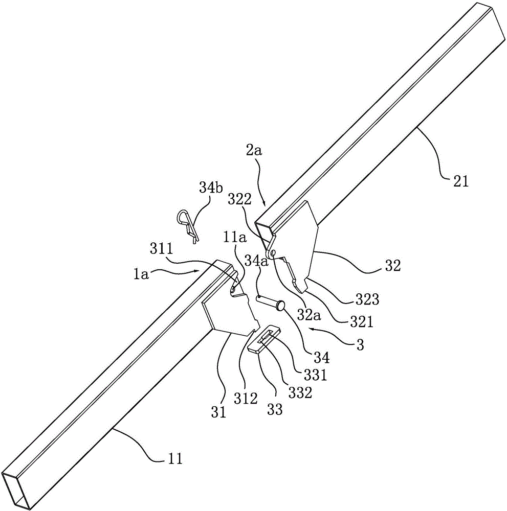
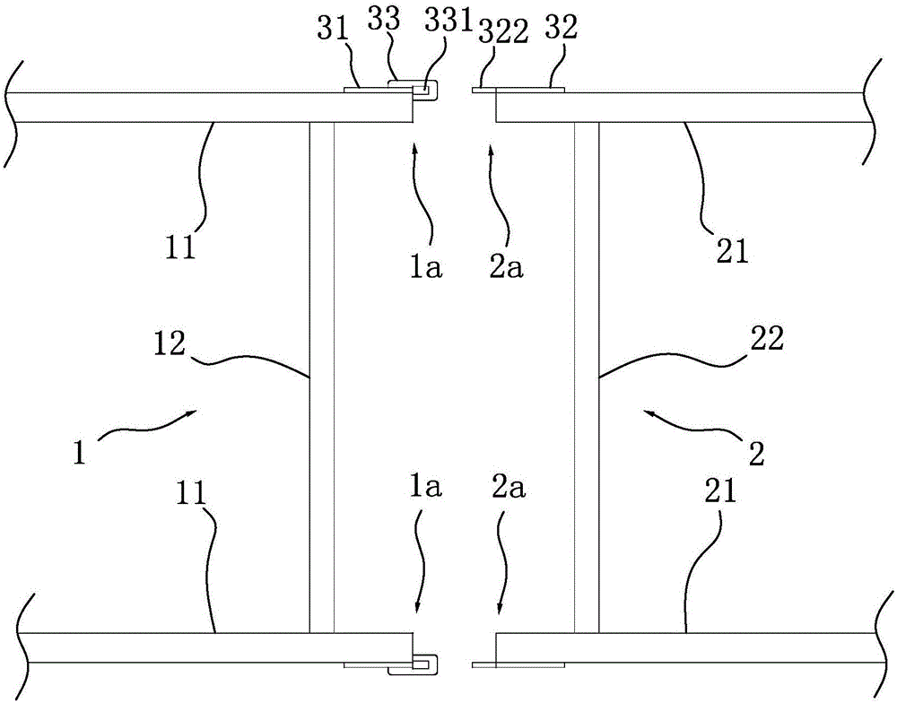
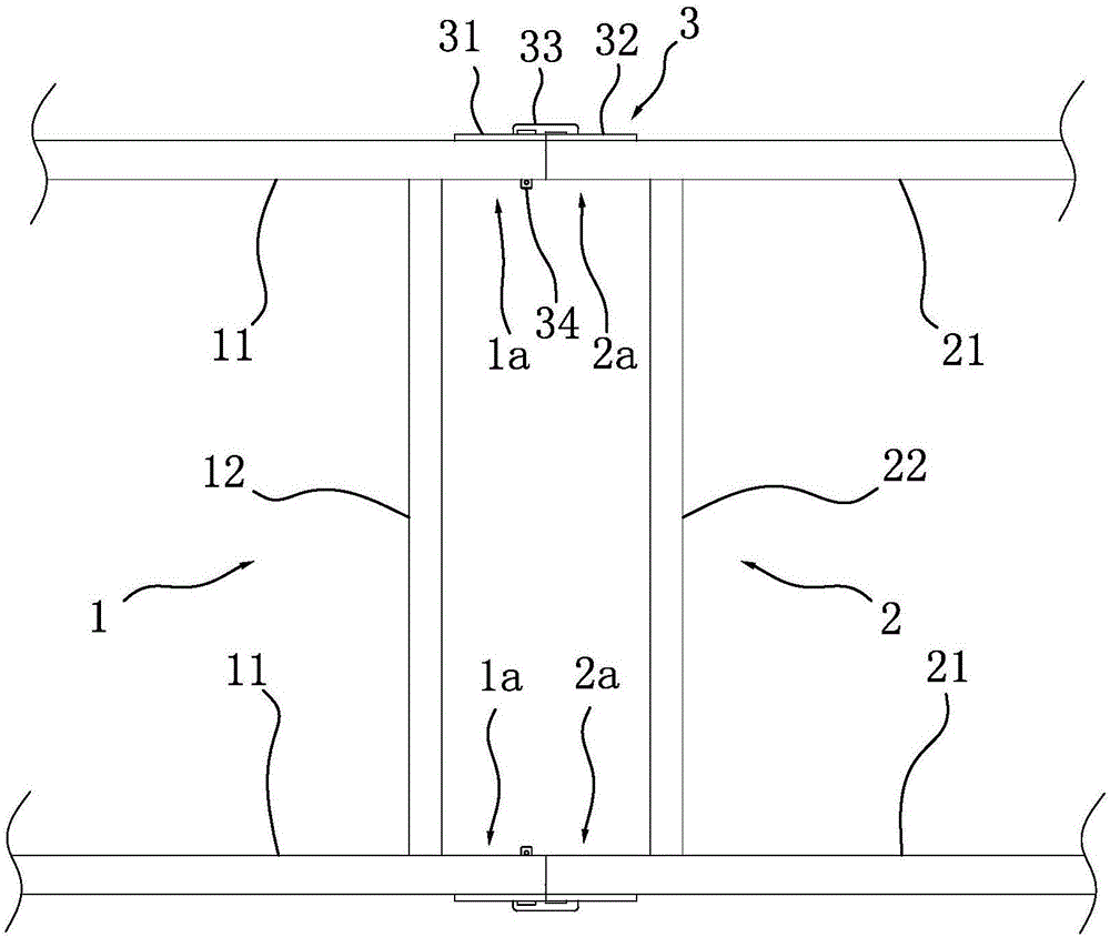
[0026] Such as Figures 1 to 3 As shown, a bed frame that is easy to assemble and disassemble includes a first bed frame 1 and a second bed frame 2. The first bed frame 1 includes two support tubes 11 arranged along the length direction and several transverse tubes arranged along the width direction. Rods 12, support tubes 11 and cross bars 12 are connected by welding to form the first bed frame 1. Similarly, the second bed frame 2 includes two support tubes 21 arranged along the length direction and several cross bars 22 arranged along the width direction. , the support pipe 21 and the cross bar 22 are connected by welding to form the second bed frame 2 . The first bed frame 1 has a first connection end 1a, the second bed frame 2 has a second connection end 2a, the first connection end 1a and the second connection end 2a are detachably connected by a connection assembly 3, and the connection assembly 3 includes a first connection Plate 31, second connecting plate 32, third c...
Embodiment 2
[0033] Such as Figure 4As shown, the difference between this embodiment and Embodiment 1 is that the fixing pin 34 includes a fixing pin body 341, a stud 342 and a pin body 343, the stud 342 is connected to the head end of the fixing pin body 341, and the pin body 343 is connected to on the head end of the stud 342. Wherein, the fixed pin body 341 is preferably configured as a columnar structure, and the diameters of the fixed pin body 341, the stud 342 and the pin body 343 are successively reduced, therefore, a step is formed between the head end surface of the fixed pin body 341 and the stud 342, The second connection plate 32 is provided with a nut 324, the nut 324 is preferably fixed on the second connection plate 32 by welding, the inner hole of the nut 324 is aligned with the second pin hole of the first embodiment, and the pin body 343 is formed by the nut. After the inner hole of 324 stretches into the second pin hole and the first pin hole, the stud 342 is threadedl...
Embodiment 3
[0035] Such as figure 1 , Figure 5 and Figure 6 As shown, the difference between this embodiment and Embodiment 1 is that the connecting assembly 3 is located inside the support tube 12, and correspondingly, the positioning pin 34b is abutted against the inner surface of the second connecting plate 32, and the pin cap is still abutted against the inner surface of the second connecting plate 32. The outer surface of the support tube 11 is supported so as to prevent the fixing pin 34 from detaching from the support tube 11 .
PUM
 Abstract
Description
Claims
Application Information
 - R&D
- Intellectual Property
- Life Sciences
- Materials
- Tech Scout
- Unparalleled Data Quality
- Higher Quality Content
- 60% Fewer Hallucinations
Browse by: Latest US Patents, China's latest patents, Technical Efficacy Thesaurus, Application Domain, Technology Topic, Popular Technical Reports.
© 2025 PatSnap. All rights reserved.Legal|Privacy policy|Modern Slavery Act Transparency Statement|Sitemap|About US| Contact US: help@patsnap.com


