Rotating shaft and electronic equipment

A shaft and axis technology, applied in the field of electronic equipment, can solve problems such as cumbersome assembly process, low production efficiency, and complex structure

Active Publication Date: 2017-05-17
HISENSE ELECTRONICS TECH SHENZHEN CO LTD
View PDF5 Cites 2 Cited by
  • Summary
  • Abstract
  • Description
  • Claims
  • Application Information

AI Technical Summary

Problems solved by technology

[0004] However, using elastic components to press the mandrel in the sleeve to fix the shaft structure, there will be many parts in the shaft structure, the specific structure is more complicated, and the assembly process is more cumbersome, and the production efficiency is lower

Method used


Image

  • Rotating shaft and electronic equipment
  • Rotating shaft and electronic equipment
  • Rotating shaft and electronic equipment

Examples


Embodiment Construction

[0016] In order to make the purpose, technical solutions and advantages of the embodiments of the present invention clearer, the technical solutions in the embodiments of the present invention will be clearly and completely described below in conjunction with the drawings in the embodiments of the present invention. Obviously, the described embodiments It is a part of embodiments of the present invention, but not all embodiments. Based on the embodiments of the present invention, all other embodiments obtained by persons of ordinary skill in the art without creative efforts fall within the protection scope of the present invention.

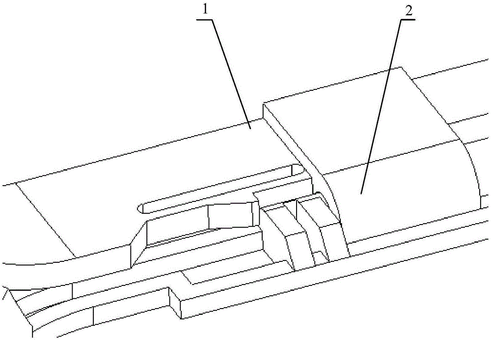
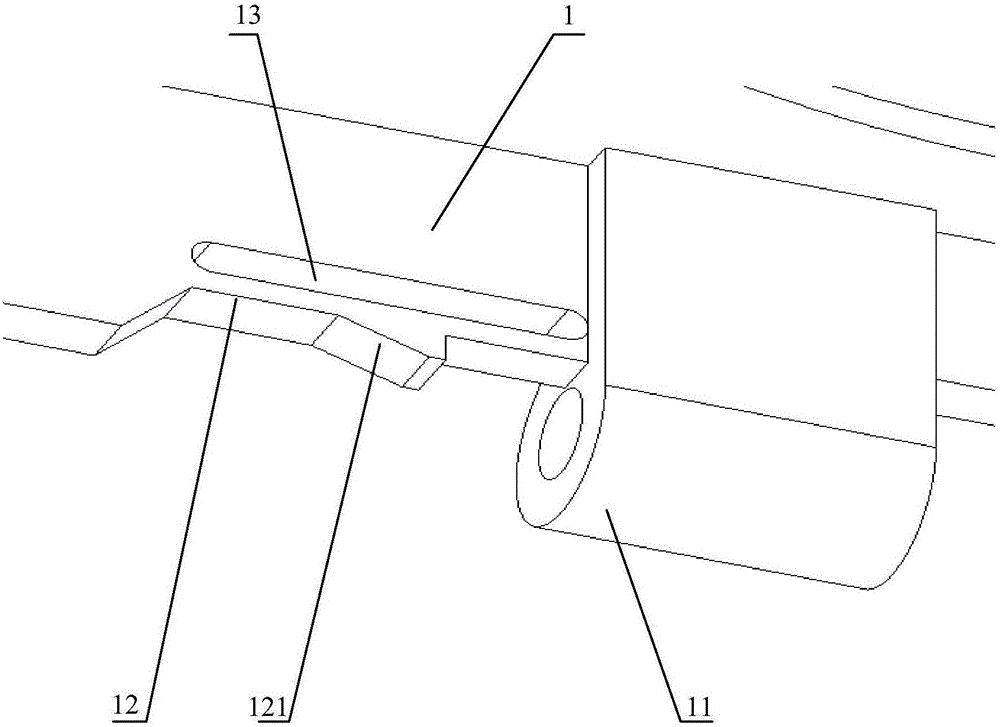
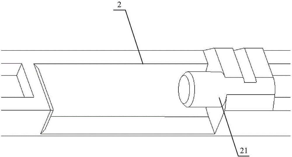
[0017] figure 1 It is a structural schematic diagram of the rotating shaft provided by Embodiment 1 of the present invention. figure 2 It is a schematic structural diagram of the first main body part provided by Embodiment 1 of the present invention. image 3 It is a schematic structural diagram of the second main body provided by Embodiment 1 ...


PUM


Abstract

The invention provides a rotating shaft and electronic equipment. The rotating shaft comprises a first main body part and a second main body part. A first rotating part on the fist main body part and a second rotating part on the second main body part can be inserted with a same axis front and back to enable the first main body part and the second main body part to be hinged together. An elastic arm is arranged on the side, provided with the first rotating part, of the first main body part and extends out in the direction parallel to the axis, and a gap is formed between the elastic arm and the side wall of the first main body part. When the elastic arm is in a free state, the position of a blocking part on the elastic arm is overlapped with the inserting position of the second rotating part and the first rotating part; and when the elastic arm is in an extruded state, the blocking part moves towards the gap along with the elastic arm to avoid the second rotating part. According to the rotating shaft, hinging rotating among different parts can be achieved, meanwhile, the structure is simple, and assembly is easy.

Description

technical field [0001] The invention relates to the field of electronic equipment, in particular to a rotating shaft and electronic equipment. Background technique [0002] With the development of science and technology, more and more different types of electronic devices appear in people's lives. [0003] At present, with the rise of virtual reality technology, there are more and more applications of various virtual reality devices. Currently, head-mounted virtual devices have become mainstream application devices. In order to adapt to wearing and realize different functions, the head-mounted virtual device needs to use the rotating shaft to generate relative rotation between different structures for various adjustments. At present, the rotating shaft structure on electronic equipment mainly includes a mandrel and a sleeve. The mandrel and the sleeve are respectively fixed on two different parts that need to produce relative rotation. The mandrel is inserted into the slee...

Claims


Application Information

Patent Timeline
Patent Type & Authority Applications(China)
IPC IPC(8): F16C11/12H05K5/02
CPCF16C11/12H05K5/0226
Inventor 周伟石自民胡罡罡
Owner HISENSE ELECTRONICS TECH SHENZHEN CO LTD
Why Eureka
Try Eureka