Sleeve shaft type differential locking mechanism

A technology of locking mechanism and differential, which is applied in the direction of differential transmission, mechanical equipment, belt/chain/gear, etc. It can solve the problems of unfavorable drive axle layout and increase in drive axle volume, so as to avoid abnormal wear and tear, The effect of reducing the overall size

Inactive Publication Date: 2017-05-17
CHINA NORTH VEHICLE RES INST
View PDF5 Cites 3 Cited by
  • Summary
  • Abstract
  • Description
  • Claims
  • Application Information

AI Technical Summary

Problems solved by technology

[0008] Most of the forced locking differentials adopt the structure of piston, shift fork and gear sleeve. The piston and the gear sleeve are not on the same axis, so that the structure of the piston and shift fork will protrude on the side of the output axis of the drive axle, which will increase the volume of the drive axle. , which is not conducive to the layout of the drive axle in the vehicle

Method used


Image

  • Sleeve shaft type differential locking mechanism
  • Sleeve shaft type differential locking mechanism
  • Sleeve shaft type differential locking mechanism

Examples


Embodiment 1

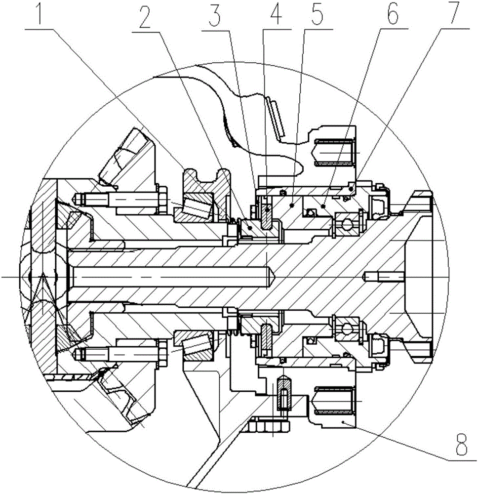
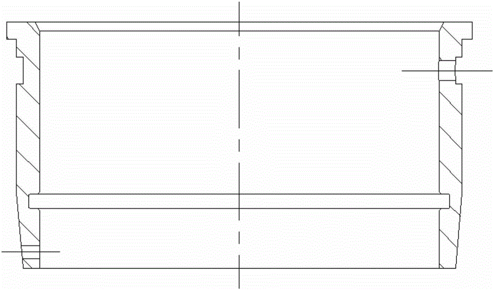
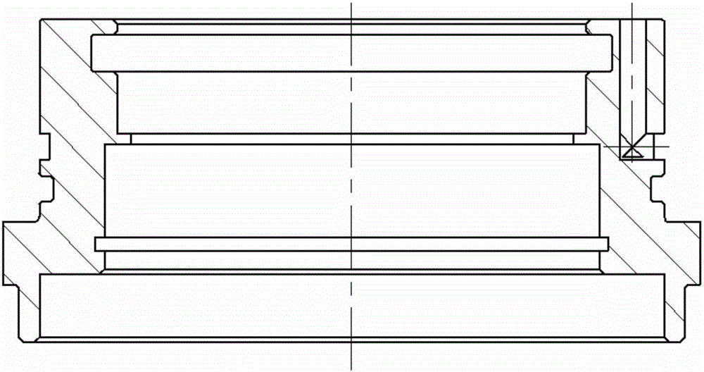
[0030] Such as Figure 1-3 As shown, it is a sleeve-type differential locking mechanism provided by the present invention. The locking mechanism is arranged on the internal half shaft of the drive axle and connected with the differential case, and includes springs 1, 1, Crankshaft 2, crankshaft support 3 for fixing the crankshaft 2, slider 4, piston 5, bearing seat 6 and steel sleeve 7 located on the outside of the above-mentioned parts, the crankset 2 and the piston 5, the piston 5 and the bearing seat 6 all adopt a coaxial structure, the piston 5 and the steel sleeve 7 are radially positioned by positioning pins, the spring 1 is connected to the tooth plate support 3, and the tooth plate 2 is fixed on the tooth plate support 3, The end of the chain plate 2 away from the spring 1 is provided with a groove, the shape of the groove is adapted to the shape of the slider 4, and the piston 5 is composed of a stepped cylinder, and the axial direction is larger than the half axis. ...

Embodiment 2

[0032] The present invention is realized in this way. When the differential gear is locked, the driver turns on the ventilation switch, and the gas with a certain pressure passes through the axle housing 8, the steel sleeve 7, and the bearing seat 6, and pushes the piston 5 to drive the tooth plate 2 and other compression springs. 1. Move towards the direction of the differential case, and the chain plate 2 is combined with the end face teeth on the differential case to realize the differential lock. When the differential lock is not needed, disconnect the air source, and the original compressed spring 1 Automatically return to the position under the action of elastic force, push the piston 5, chainring support 3, and chainring 2 to move away from the differential until the piston 5 is close to the end face of the bearing seat 6, and the teeth on the end face of the piston 5 are in contact with the end face of the differential case The teeth are separated. When the differential...


PUM


Abstract

The invention provides a sleeve shaft type differential locking mechanism. The locking mechanism is arranged on a half shaft in a drive axle and connected with a differential shell, and comprises a spring, a chain wheel, a chain wheel bracket for fixing the chain wheel, a slide block, a piston, a bearing base and a steel sleeve arranged on the outer sides of the parts, which are arranged in the same one axial direction in sequence; and the chain wheel and the piston, the piston and the bearing base, and the piston and the steel sleeve are all coaxial. The locking mechanism adopts a more compact structure to realize a differential locking function, prevents the structure of projecting such devices as a poking fork on the side surface of an output end, reduces the total size of the drive axle, radially positions the piston and the steel sleeve through dowel pins, and prevents the piston from rotating in the working process to cause abnormal wear.

Description

[0001] Technical field: [0002] The invention relates to a locking mechanism, in particular to a sleeve shaft differential locking mechanism. [0003] Background technique: [0004] The drive axle of the vehicle is located at the end of the drive train, and its basic function is to increase the torque transmitted from the drive shaft or directly from the transmission, and distribute the torque to the left and right drive wheels to drive the car. [0005] The drive axle is mainly composed of final reducer, differential, axle housing and left and right half shaft assemblies. The main reducer is composed of a pair of bevel gears. Its function is to reduce the speed and increase the torque transmitted by the transmission shaft, transmit it to the differential, and turn the rotation plane of the transmission shaft at an angle of 90°. A pair of bevel gears in the final drive are respectively supported by a pair of bevel bearings. The function of the differential is to separate the...

Claims


Application Information

Patent Timeline
Patent Type & Authority Applications(China)
IPC IPC(8): F16H48/32F16H48/38F16H48/40
Inventor 郭婷马贵叶吴超李晋张芃赵凯张祖智张静刘亚成
Owner CHINA NORTH VEHICLE RES INST
Why Eureka
Try Eureka