Heating power switching system for solar thermal collector heat collection pipes

A solar collector and switching system technology is applied in the field of thermal switching systems for solar collectors and collector tubes, which can solve the problems of reduced service life and failure of the collector tubes to meet design operating conditions, so as to increase operational reliability and improve thermal fatigue. And the cold section can not reach the design operating conditions of the collector tube for a long time, and the effect of prolonging the service life

Active Publication Date: 2017-05-17
陈宇奇
View PDF5 Cites 0 Cited by
  • Summary
  • Abstract
  • Description
  • Claims
  • Application Information

AI Technical Summary

Problems solved by technology

Due to thermal fatigue, the life of the heat collecting tube in the hot section will be greatly reduced, and the heat collecting tube in the cold section will not reach the design working condition for a long time
For this problem, there is still no solution at home and abroad to solve this problem

Method used


Image

  • Heating power switching system for solar thermal collector heat collection pipes
  • Heating power switching system for solar thermal collector heat collection pipes

Examples


Embodiment 1

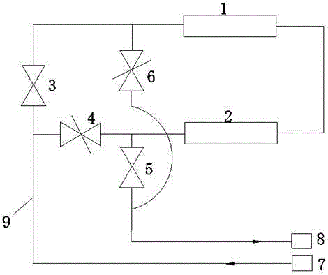
[0028] like figure 1 As shown in the figure, a thermal switching system of a solar collector tube mainly includes a first collector 1, a second collector 2, a first valve 3, a second valve 4, a third valve 5, and a fourth valve 6 And the heat-carrying medium inlet 7 and the heat-carrying medium outlet 8, the heat-carrying medium inlet 7 is respectively connected to one end of the first valve 3 and one end of the second valve 4 through the heat pump working medium circulation pipe 9, and the other end of the first valve 3 is respectively connected One end of the fourth valve 6 and one end of the first collector 1, the other end of the first collector 1 is connected to one end of the second collector 2, and the other end of the second collector 2 is connected to the other end of the second valve 4 and the third valve One end of 5, the other end of the fourth valve 6 is connected to the other end of the third valve 5, and the other end of the third valve 5 is connected to the he...

Embodiment 2

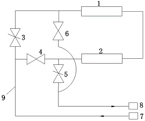
[0037] like figure 2 As shown in the figure, a thermal switching system of a solar collector tube mainly includes a first collector 1, a second collector 2, a first valve 3, a second valve 4, a third valve 5, and a fourth valve 6 And the heat-carrying medium inlet 7 and the heat-carrying medium outlet 8, the heat-carrying medium inlet 7 is respectively connected to one end of the first valve 3 and one end of the second valve 4 through the heat pump working medium circulation pipe 9, and the other end of the first valve 3 is respectively connected One end of the fourth valve 6 and one end of the first collector 1, the other end of the first collector 1 is connected to one end of the second collector 2, and the other end of the second collector 2 is connected to the other end of the second valve 4 and the third valve One end of 5, the other end of the fourth valve 6 is connected to the other end of the third valve 5, and the other end of the third valve 5 is connected to the he...


PUM


Abstract

The invention mainly provides a heating power switching system for solar thermal collector heat collection pipes. The heating power switching system mainly comprises a first solar thermal collector, a second solar thermal collector, a first valve, a second valve, a third valve, a fourth valve, a heat-carrying working medium inlet and a heat-carrying working medium outlet. The heat-carrying working medium inlet is connected with the first valve and the second valve through a heat pump working medium circulating pipe. The first valve is connected with one end of the fourth valve and one end of the first solar thermal collector. The other end of the first solar thermal collector is connected with one end of the second solar thermal collector. The other end of the second solar thermal collector is connected with the second valve and one end of the third valve. The other end of the fourth valve is connected with the other end of the third valve. The other end of the third valve is connected with the heat-carrying working medium outlet through a heat pump working medium circulating pipe. The heating power switching system is simple in structure principle, the purpose of heating power state switching can be achieved by changing the flow direction of heat-carrying working media in a heat production circulating loop, the service life of the heat collection pipes is prolonged, and operational reliability of a heat production circulating loop system is improved.

Description

technical field [0001] The invention relates to the field of solar thermal collectors, in particular to a thermal switching system of a solar thermal collector heat collecting tube. Background technique [0002] A solar collector is a device that converts the radiant energy of the sun into thermal energy. Since the solar energy is relatively scattered, we must try to concentrate it, so the collector is a key part of various solar energy installations. Due to different uses, collectors and their matching system types are divided into many types with different names, such as solar cookers for cooking, solar water heaters for producing hot water, solar dryers for drying items, Solar furnaces for smelting metals, as well as solar houses, solar thermal power plants, solar desalinators, and more. A solar collector is a device that absorbs solar radiation and transfers the generated thermal energy to a heat transfer medium. This short definition contains rich meanings: first: a ...

Claims


Application Information

Patent Timeline
Patent Type & Authority Applications(China)
IPC IPC(8): F24J2/40
CPCY02E10/40
Inventor 陈宇奇
Owner 陈宇奇
Why Eureka
Try Eureka