Heat sink and manufacturing method thereof

A technology of heat dissipation device and manufacturing method, which is applied in semiconductor/solid-state device manufacturing, electrical components, electric solid-state devices, etc., which can solve problems such as damage to luminous body, increase of thermal resistance of joint interface, heat accumulation, etc., and improve the problem of cracking of joint interface Effect

Active Publication Date: 2015-12-02
ASIA VITAL COMPONENTS SHENZHEN CO LTD
View PDF11 Cites 0 Cited by
  • Summary
  • Abstract
  • Description
  • Claims
  • Application Information

AI Technical Summary

Problems solved by technology

[0007] Furthermore, for example, in the application field of LED heat dissipation, the thermal expansion coefficient of aluminum and copper materials is much higher than that of sapphire, which may easily lead to the joint interface due to thermal fatigue on the joint surface of high-brightness LEDs under long-term use. Crack, resulting in an increase in the thermal resistance of the joint interface
For high-brightness LED products, when the thermal resistance of the heat dissipation interface rises, it will cause heat accumulation and damage the LED chip, resulting in permanent damage to the luminous body

Method used


Image

  • Heat sink and manufacturing method thereof
  • Heat sink and manufacturing method thereof
  • Heat sink and manufacturing method thereof

Examples


Embodiment Construction

[0035] The above-mentioned purpose of the present invention and its structural and functional characteristics will be described based on the preferred embodiments of the accompanying drawings.

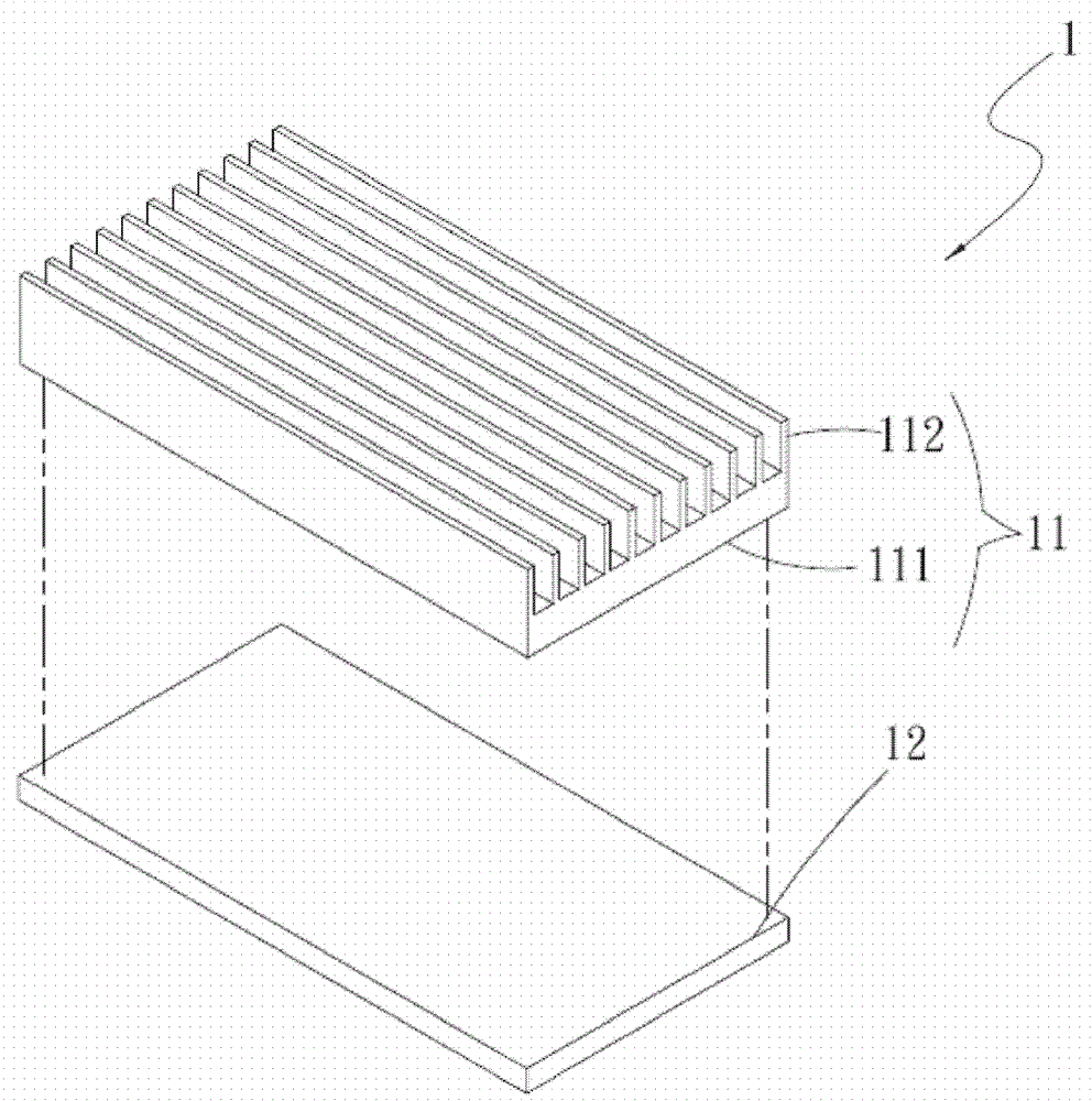
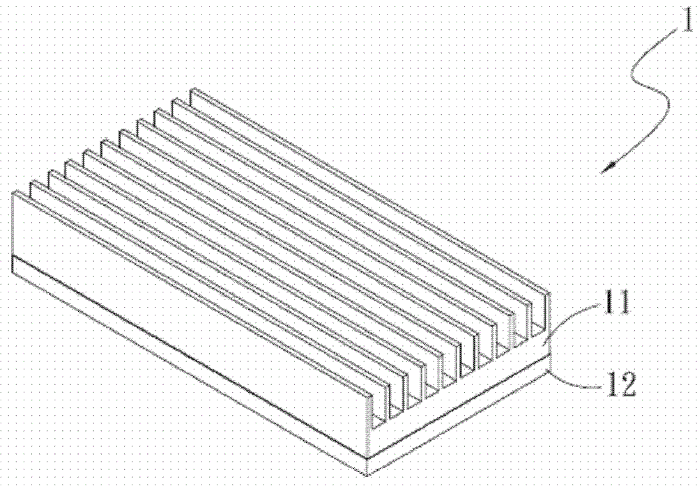
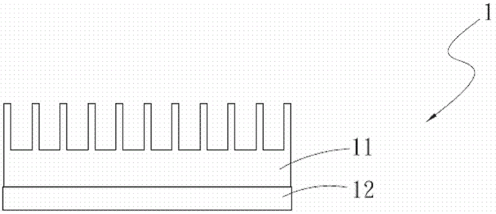
[0036] see Figure 1a , Figure 1b , figure 2 , is the three-dimensional exploded and assembled view and the front view of the first embodiment of the heat dissipation device of the present invention. As shown in the figure, the heat dissipation device 1 includes: a heat dissipation element 11;

[0037] The heat dissipation element 11 has a heat conduction portion 111, and the other end of the heat dissipation element 11 opposite to the heat conduction portion 111 has a heat dissipation portion 112, and the heat conduction portion 111 is connected to a ceramic body 12. In this embodiment, the heat dissipation element 11 It is a radiator, and the material of the ceramic body 12 is silicon nitride (Si 3 N 4 ), zirconia (ZrO 2 ), alumina (Al 2 o 3 ) either.

[0038] see image 3 ...


PUM


Abstract

The invention provides a heat radiation device and a manufacturing method thereof. The heat radiation device comprises a heat radiation element, wherein the heat radiation element is provided with a heat conduction part; a heat radiation part is arranged at the other end of the heat conduction part, which is opposite to the heat radiation element; the heat conduction part is connected with a ceramic body; and the heat radiation device is directly combined with the ceramic body through a welding and direct copper covering manner, so that the problem that a joint interface is crushed by thermal fatigue between the heat radiation device and a heating source is solved.

Description

technical field [0001] A heat dissipation device and its manufacturing method, especially a heat dissipation device and its manufacturing method that directly combine a heat dissipation element with a ceramic element to improve the cracking problem of the junction between the heat dissipation device and the heat source due to thermal fatigue (thermal fatigue) . Background technique [0002] By the way, with the advancement of semiconductor technology, the volume of integrated circuits is gradually shrinking. In order to enable integrated circuits to process more data, integrated circuits with the same volume can accommodate several times more than before. Computing elements. When the number of computing elements in the integrated circuit increases, the heat energy generated by the computing elements will also increase. Taking the common central processing unit as an example, when the workload is high and full, the central processing unit The heat emitted by the circuit brea...

Claims


Application Information

Patent Timeline
Patent Type & Authority Patents(China)
IPC IPC(8): H01L23/36H01L23/373H01L21/48
Inventor 杨修维
Owner ASIA VITAL COMPONENTS SHENZHEN CO LTD
Why Eureka
Try Eureka