Method of processing metal members

A technology of metal components and components, applied in the direction of metal processing equipment, manufacturing tools, non-electric welding equipment, etc., can solve the problems of reducing the fatigue strength of metal components and making them unusable

Inactive Publication Date: 2002-08-28
MAZDA MOTOR CORP
View PDF1 Cites 7 Cited by
  • Summary
  • Abstract
  • Description
  • Claims
  • Application Information

AI Technical Summary

Problems solved by technology

[0005] However, in the connection technology described in the above-mentioned patent, since the probe is inserted into the surface of the metal member and moves, there will be welding traces (holes) at the start and end points of the probe movement track
This causes problems related to the appearance of the metal member, that

Method used


Image

  • Method of processing metal members
  • Method of processing metal members
  • Method of processing metal members

Examples


Embodiment Construction

[0055] Embodiments of the present invention will be described in detail below with reference to the accompanying drawings.

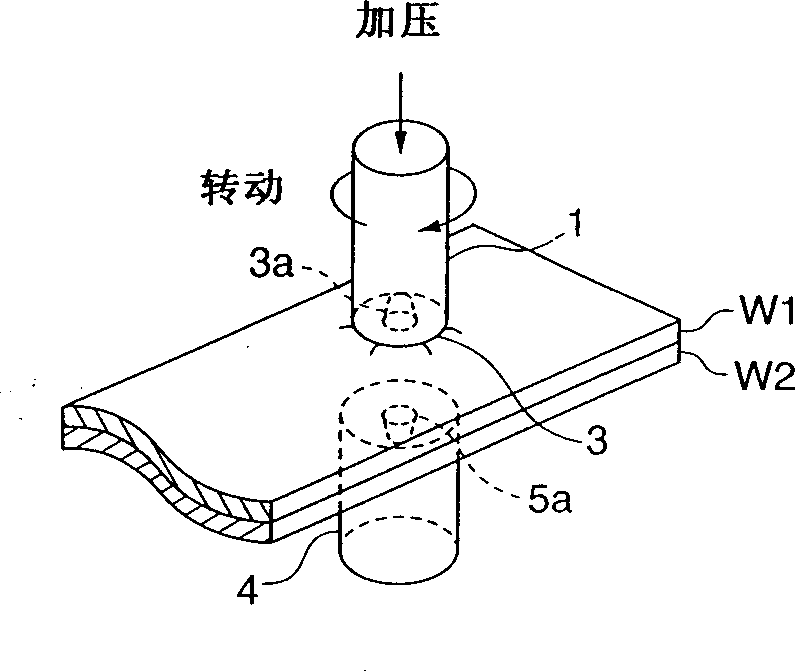
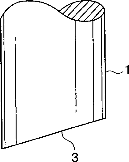
[0056] Referring now to FIG. 1, which shows an enlarged view of a rotary tool and its vicinity, a lap joint method according to one embodiment of the present invention is illustrated.

[0057] The connection method of the present invention is used to connect metal components such as aluminum alloy plates and those metal components that have been pressed into a three-dimensional shape, and is to connect the first and second metal components W1, W2 according to the following steps: overlap at least two metal components ; a rotating tool 1 is pressed on the overlapping member, that is, the outermost surface of the first metal member W1; metal structure while maintaining it in a non-molten state.

[0058] In this way, since the metal structure is agitated while being kept in a non-melted state, problems such as thermal deformation caused by resistance welding...


PUM


Abstract

The first and second metal members (W1, W2) are connected by the following steps: overlapping at least two metal members with each other; pressing a rotary tool (1) on the outermost surface of the overlapping metal members, i.e., Pressed on the first metal member (W1); the frictional heat generated by the rotation of the rotating tool (1) stirs the metal structure between the first and second metal members (W1, W2), while maintaining the metal member in a non-melted state .

Description

technical field [0001] The present invention relates to methods of machining metal components such as aluminum alloy castings and plates. Background technique [0002] In the current joining technology, metal components such as plates or those that have been pressed into a three-dimensional shape are overlapped with each other and connected using resistance welding or arc welding, joining materials, bolt fastening, riveting, etc. [0003] If the metal member exhibits a complicated three-dimensional shape, a spot welding method is used in which a plurality of parts to be welded scattered on the metal member can be locally welded. [0004] As another joining technique, Japanese Patent No. 2712838 discloses a joining method in which metal members are stirred by friction while remaining in a non-melted state. This joining technique joins two metal parts in the following steps: At the point where the two metal parts butt together, a protruding part called a probe is inserted int...

Claims


Application Information

Patent Timeline
IPC IPC(8): B23K20/12
CPCB23K20/123B23K20/1255B23K20/1265B23K20/12
Inventor 玄道俊行野村诚治
Owner MAZDA MOTOR CORP
Why Eureka
Try Eureka