Rolling ball force transmission type low-speed high-torque hydraulic motor

A low-speed, high-torque, hydraulic motor technology, applied in the field of fluid transmission and control, hydraulic pressure, can solve the problems of low motor volume efficiency, wear of the plunger cavity wall, frequent plunger replacement, etc., achieve high mechanical efficiency, improve sealing performance, The effect of refined structure

Active Publication Date: 2019-06-14
BEIJING UNIV OF TECH
View PDF5 Cites 0 Cited by
  • Summary
  • Abstract
  • Description
  • Claims
  • Application Information

AI Technical Summary

Problems solved by technology

[0002] The low-speed and high-torque hydraulic motor uses high-pressure liquid as the working medium, which plays an important role in the components of the hydraulic system, and its performance plays a decisive role in the hydraulic system; The plunger roller motor, although the plunger ball and plunger roller motors reduce the number of parts to a certain extent, but there is a serious problem of lateral force on the wall of the plunger cavity; therefore, the volumetric efficiency of the motor is low, A series of problems such as large leakage, short life, frequent replacement of plunger, etc.
At present, many scientific research institutions are committed to researching bionic surfaces to reduce the large leakage caused by friction and wear, but they have not fundamentally solved the problem of serious wear of the plunger caused by large lateral forces

Method used


Image

  • Rolling ball force transmission type low-speed high-torque hydraulic motor
  • Rolling ball force transmission type low-speed high-torque hydraulic motor
  • Rolling ball force transmission type low-speed high-torque hydraulic motor

Examples


Embodiment Construction

[0025] The following will be combined with Figure 1-5 The present invention is described in further detail:

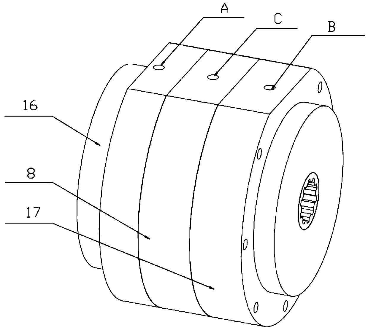
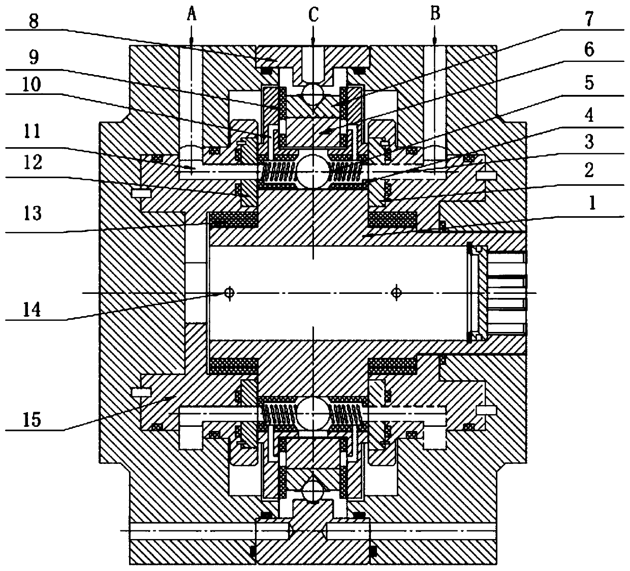
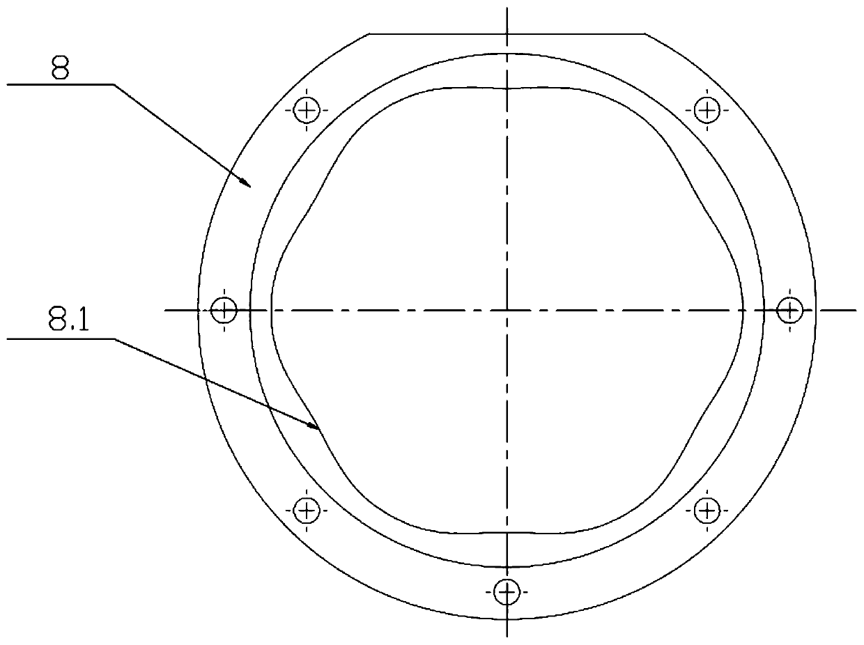
[0026] Such as figure 1 As shown, the rear end cover 16 and the front end cover 17 are connected to the inner curved stator 8 by screws, and an inlet A is opened on the rear end cover 16, and a leakage port C is opened on the inner curved stator 8, and the high-pressure liquid passes through the inlet A , The distribution fluid 15 communicates with the left distribution plate 12 and the inlet flow channel 11; the stator inner curve 8.1 in the inner curved stator 8 is in contact with the rolling ball 7.1 and is rolling friction; the front end cover 17 has an outlet B through the distribution fluid 15 It communicates with the right valve plate 2 through the outlet flow channel 3, and the inlet A, outlet B and leakage port C are set on the same plane, which not only reduces the processing difficulty but also makes the motor structure more reasonable and compact.

[002...


PUM


Abstract

The invention discloses a ball force transferring type low-speed large-torque hydraulic motor. According to the hydraulic motor, high-pressure liquid enters a flow distribution body and thrust plates from a rear end cover to act on a shuttle valve so as to introduce the high-pressure liquid into a plunger cavity; the pressure of the high-pressure liquid acts on a plunger and a transfer block, the force is transferred to an inner curve type stator through balls on the transfer block, and the balls rotate along the inner curve type stator under the reactive force; and when the balls move to the highest point to complete the lifting stroke along with the rotation of a rotor, at the moment, an inlet is closed, an outlet is opened, the shuttle valve is restored to the equilibrium position under the action of the spring force, the balls start to return along the inner curve, and the liquid in the plunger cavity flows out through the outlet. The hydraulic motor has the advantages that the structure is reasonable and compact, the plunger and the transfer block are adopted so that leakage of the plunger cavity caused by the radial force can be effectively avoided, the balls are adopted to do rolling friction along the inner curve, and an annular lubricating groove is formed in the inner curve type stator so that the effect of lubricating the balls and reducing frictional wear can be achieved.

Description

technical field [0001] The invention belongs to the field of hydraulic technology, relates to a radial plunger type low-speed high-torque hydraulic motor, in particular to a rolling ball force transmission type low-speed high-torque hydraulic motor, which is mainly used in hydraulic transmission systems and belongs to the technical field of fluid transmission and control. Background technique [0002] The low-speed and high-torque hydraulic motor uses high-pressure liquid as the working medium, which plays an important role in the components of the hydraulic system, and its performance plays a decisive role in the hydraulic system; The plunger roller motor, although the plunger ball and plunger roller motors reduce the number of parts to a certain extent, but there is a serious problem of lateral force on the wall of the plunger cavity; therefore, the volumetric efficiency of the motor is low, There are a series of problems such as large leakage, short life, frequent replace...

Claims


Application Information

Patent Timeline
Patent Type & Authority Patents(China)
IPC IPC(8): F15B15/08F15B15/20
CPCF15B15/08F15B15/20
Inventor 聂松林申文强
Owner BEIJING UNIV OF TECH
Why Eureka
Try Eureka