A low-speed and high-torque hydraulic motor with two-end plate flow distribution

A low-speed, high-torque, hydraulic motor technology, applied in the field of fluid transmission and control, hydraulic pressure, can solve the problems of low volumetric efficiency, large leakage, short life, etc., to achieve the effect of improving volumetric efficiency, increasing service life, and reducing overall replacement

Active Publication Date: 2019-06-07
BEIJING UNIV OF TECH
View PDF4 Cites 0 Cited by
  • Summary
  • Abstract
  • Description
  • Claims
  • Application Information

AI Technical Summary

Problems solved by technology

[0002] The low-speed high-torque hydraulic motor uses high-pressure liquid as the working medium, and plays an important role in the components of the hydraulic system. Its quality determines the performance of the hydraulic system; but the low-speed high-torque hydraulic motor with the same end face distribution is widely used at present. , although the flow distribution on the same end face can reduce the volume of the motor components to a certain extent, there is a problem of high and low liquid communication on the same flow plate; only relying on the gap seal will form high and low pressure fluids to communicate with each other on the end face, which will inevitably lead to volumetric efficiency Low, large leakage, short life and a series of problems
At present, domestic and foreign are mainly working on increasing or reducing the sealing band on the distribution plate or using static pressure support to solve such problems, and some research institutions are studying the leakage problem by appropriately changing the inner curve structure and the number of plunger pairs; Therefore, the traditional low-speed high-torque hydraulic motor has not fundamentally solved the problem of high and low pressure fluid communicating through the sealing gap

Method used


Image

  • A low-speed and high-torque hydraulic motor with two-end plate flow distribution
  • A low-speed and high-torque hydraulic motor with two-end plate flow distribution
  • A low-speed and high-torque hydraulic motor with two-end plate flow distribution

Examples


Embodiment Construction

[0024] The present invention will be described in further detail below in conjunction with accompanying drawing:

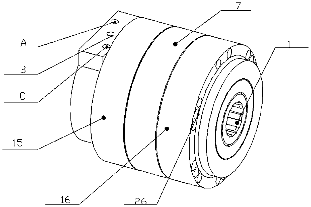
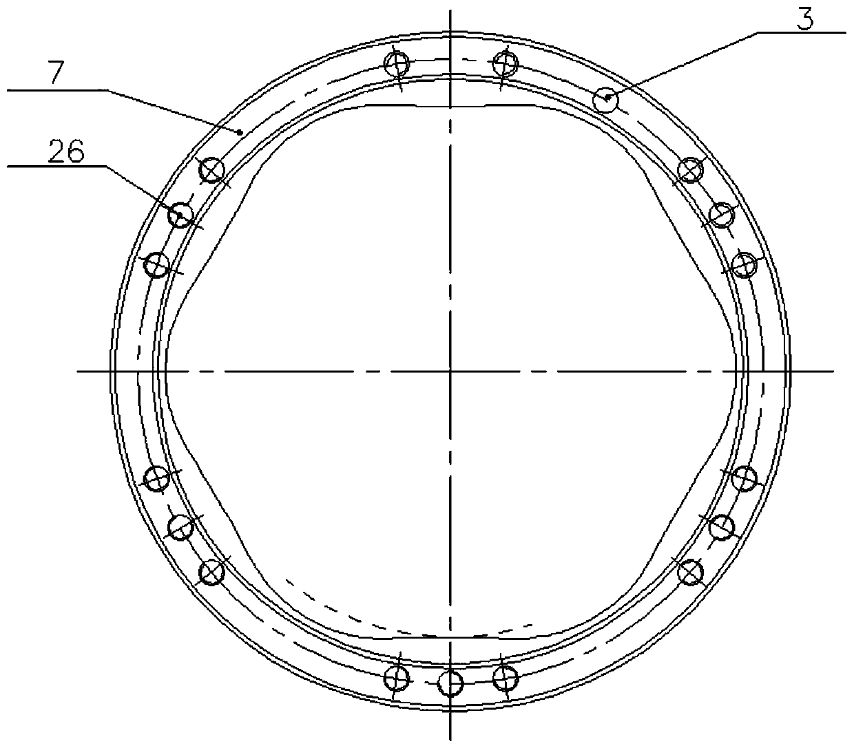
[0025] Such as figure 1 As shown, the rear end cover 15 and the stator 7, the front end cover 16 and the stator 7 are all connected through screw holes 26, and there are three holes on the rear end cover 15, which are inlet A, outlet B and leakage port C respectively; The end cover 15 and the front end cover 16 are connected by a flat key to prevent the right valve plate 2 and the left valve plate 12 from rotating together due to the friction force of the rotor 1; there is an internal spline protruding from the rotor 1 on the front end cover 16, which is convenient for contact with the external load connection, which greatly reduces the overall volume of the motor and improves the mechanical efficiency of the motor.

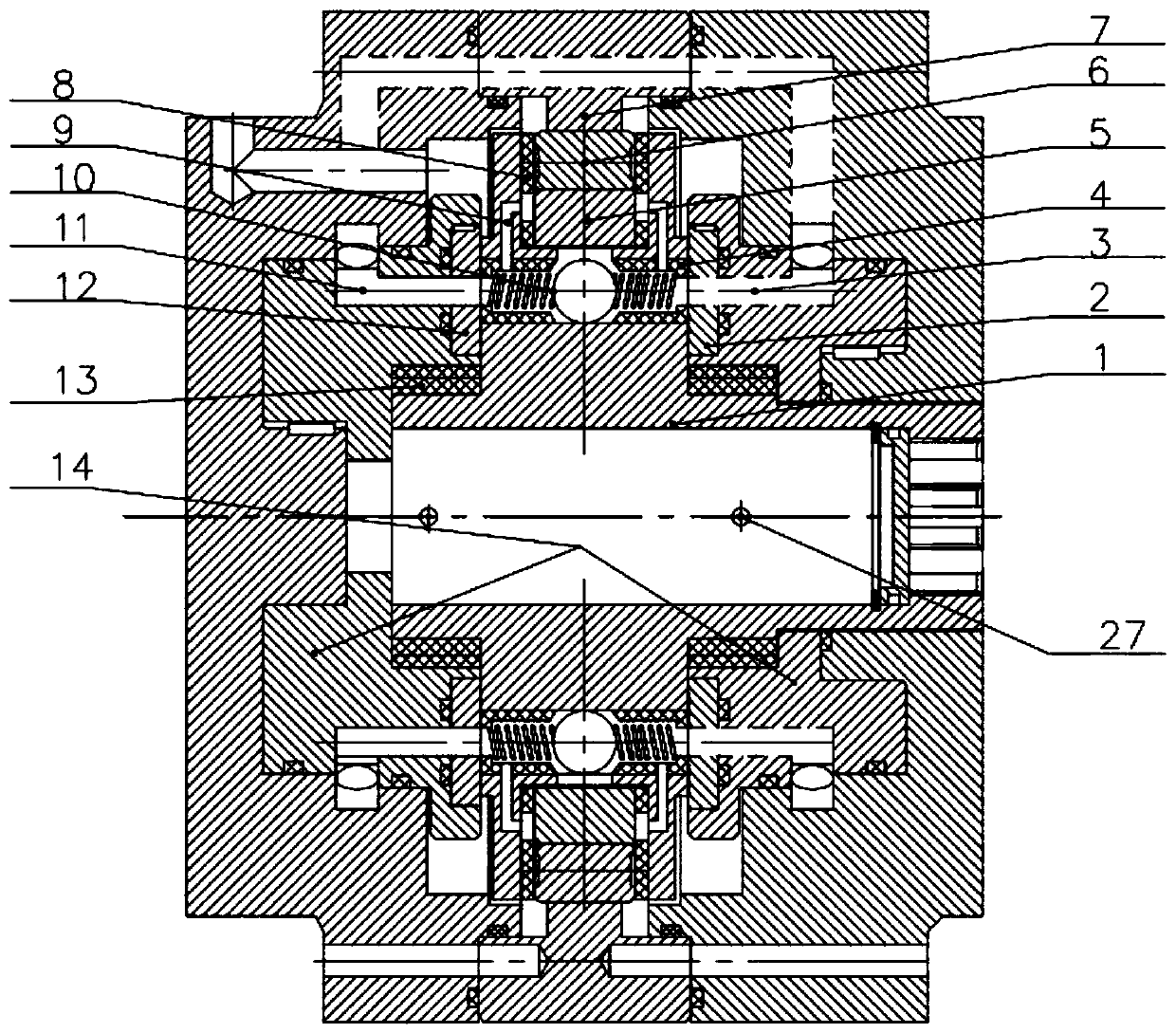
[0026] Such as figure 2 As shown, the rotor 1 is equipped with 10 plungers 5 and 10 ball valves 10 respectively, a sliding bearing 13 is install...


PUM


Abstract

The invention discloses a two-end disc flow-distribution type low-speed large-torque hydraulic motor comprising flow-distribution bodies, plunger pairs, plunger linings, ball valves, ball valve sleeves, flow-distribution discs, a rotor, an inlet, an outlet and an inner curve type stator. High-pressure liquid is guided to flow to inlets of the flow-distribution discs and acts on the ball valves toenable valve balls to seal the outlet end; after the high-pressure liquid enters plunger cavities to push plungers to move to the highest points, along with rotation of the rotor, the inlet is sealedand the outlet is opened at the moment, and the plungers move to the topmost ends under pushing of the high-pressure liquid so as to complete lift; and then, part of the high-pressure liquid in the plunger cavities is made to enter the outlet through plunger sleeve flow channels, the ball valves are pushed back to the initial positions under the effect of spring force, at the moment, the plungersstart to conduct return stroke, the high-pressure liquid in the plunger cavities flows out through the outlet, and thus the plungers finish the return stroke. The two-end disc flow-distribution type low-speed large-torque hydraulic motor is reasonable, compact and convenient to use, the volume efficiency is greatly improved, and high-pressure and low-pressure liquid inlets and outlets are formed in the same end of the motor, so that the structure is more compact.

Description

technical field [0001] The invention belongs to the technical field of hydraulic pressure, relates to a low-speed high-torque hydraulic motor, in particular to a low-speed high-torque hydraulic motor of a two-end plate flow distribution type, and belongs to the technical field of fluid transmission and control. Background technique [0002] The low-speed high-torque hydraulic motor uses high-pressure liquid as the working medium, and plays an important role in the components of the hydraulic system. Its quality determines the performance of the hydraulic system; but the low-speed high-torque hydraulic motor with the same end face distribution is widely used at present. , although the flow distribution on the same end face can reduce the volume of the motor components to a certain extent, there is a problem of high and low liquid communication on the same flow plate; only relying on the gap seal will form high and low pressure fluids to communicate with each other on the end f...

Claims


Application Information

Patent Timeline
Patent Type & Authority Patents(China)
IPC IPC(8): F03C2/08
Inventor 聂松林申文强
Owner BEIJING UNIV OF TECH
Why Eureka
Try Eureka