
Detection mechanism with side light source configured for annular light source and backlight source for AOI (Automated Optical Inspection) visual inspection

A ring light source and visual detection technology, which is applied to measuring devices, material analysis through optical means, instruments, etc., can solve problems such as insufficient lighting and uneven lighting, and achieve good lighting effects and accurate results.

Pending Publication Date: 2017-05-17
苏州富鑫林光电科技有限公司
View PDF11 Cites 14 Cited by
  • Summary
  • Abstract
  • Description
  • Claims
  • Application Information

AI Technical Summary

Problems solved by technology

[0003] The purpose of the present invention is to provide a detection mechanism for AOI visual detection, which can solve the problem of insufficient and uneven lighting during detection, and because the lighting effect is good, the photos taken by the CCD camera are of better quality, so It is more accurate to judge the results of AOI visual appearance inspection of Cell products

Method used


Image

  • Detection mechanism with side light source configured for annular light source and backlight source for AOI (Automated Optical Inspection) visual inspection
  • Detection mechanism with side light source configured for annular light source and backlight source for AOI (Automated Optical Inspection) visual inspection
  • Detection mechanism with side light source configured for annular light source and backlight source for AOI (Automated Optical Inspection) visual inspection

Examples


Embodiment

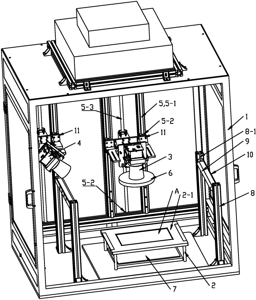
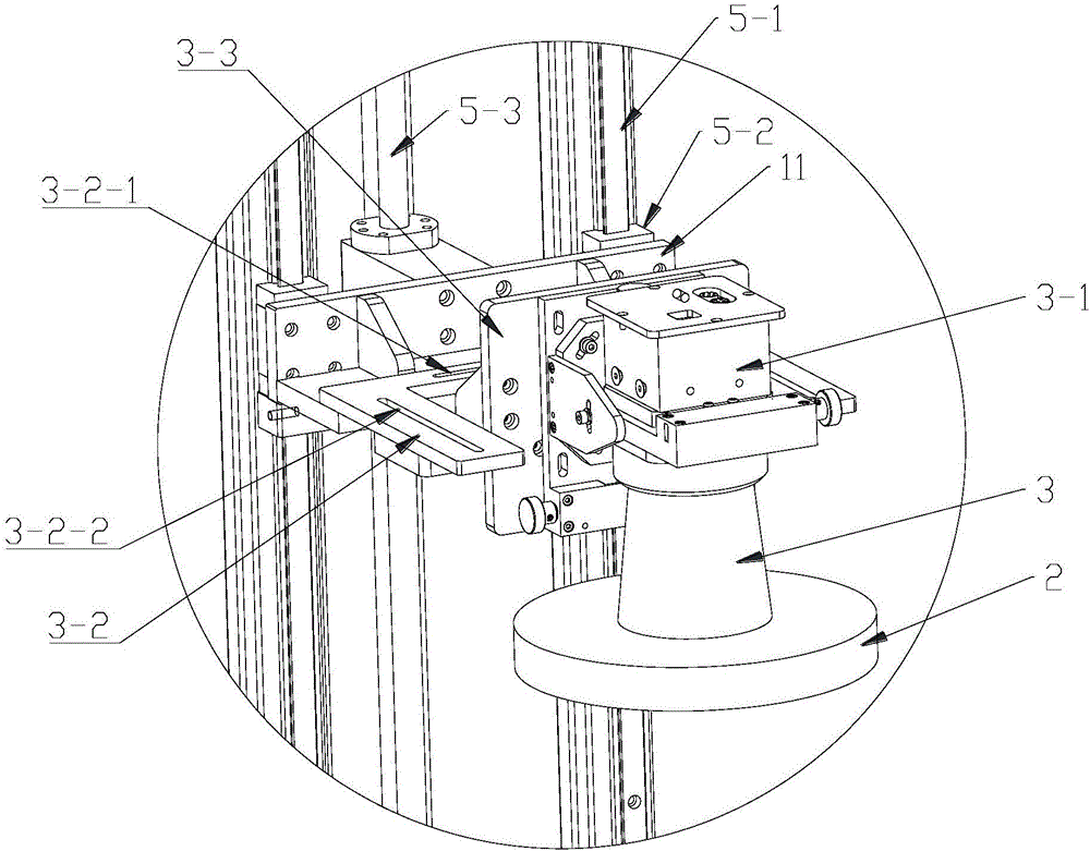
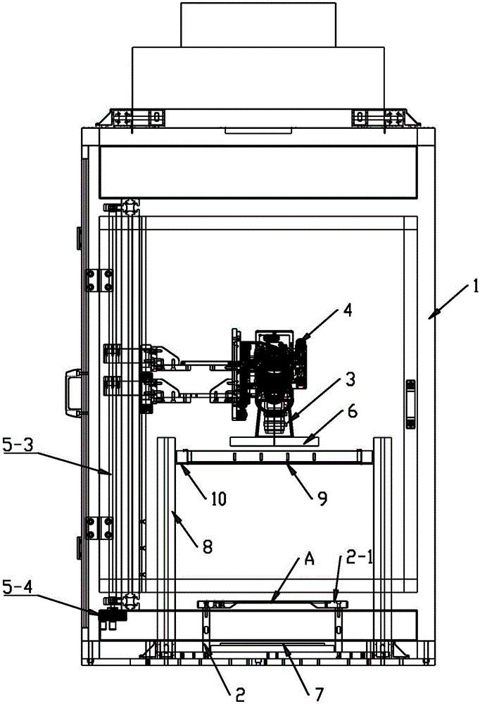
[0027] Example: such as Figure 1 to Figure 3 As shown, a ring light source for AOI visual inspection is equipped with a side light source and a backlight detection mechanism, including a bracket 1 and a CCD camera. The bracket 1 has a detection area, and the bracket 1 is provided with a support frame 2 in the detection area. 2 The top is provided with a mounting bracket 2-1 for fixing the product A to be inspected, and a backlight 7 is provided directly below the bracket 1 relative to the product A to be inspected. The CCD camera includes a front view CCD camera 3 located directly above the inspection area and The side viewing angle CCD camera 4 that is positioned at the detection area side, described positive viewing angle CCD camera 3 is installed and fixed with the annular light source 6 below its lens, and described support 1 is respectively provided with for facing toward the left and right side top of support frame 2. The high-angle strip light source 9 for lighting the...


PUM


Abstract

The invention discloses a detection mechanism with a side light source configured for an annular light source and a backlight source for AOI (Automated Optical Inspection) visual inspection. The detection mechanism comprises a stand and a CCD (Charge Coupled Device) camera. The stand is provided with a support frame, wherein the top of the stand is provided with a mounting rack for fixing a product to be detected, the backlight source is arranged under the product to be detected relative to the stand, the CCD camera comprises a central view CCD camera positioned right above a detection area and a side view CCD camera positioned on the side surface of the detection area, the annular light source is fixedly installed below a camera lens of the center view CCD camera, the stand is provided with high-angle strip-shaped light sources for lighting towards the detection area respectively above the left and right sides of the support frame, and the heights of the center view CCD camera and the side view CCD camera can be adjusted up and down relative to the stand through a corresponding up-and-down sliding mechanism. The detection mechanism can solve the problem that the lighting is insufficient and uneven during AOI visual inspection.

Description

technical field [0001] The invention relates to the field of AOI visual detection, in particular to a detection mechanism for AOI visual detection. Background technique [0002] The inspection mechanism in the existing AOI visual inspection device is relatively simple, and it is all supplemented by the light source of the incandescent lamp, which cannot solve the problem of insufficient and uneven lighting during the AOI visual appearance inspection. However, due to the poor lighting effect, the quality of the photos taken by the CCD camera (CCD image sensor) is not high, so the results of the AOI visual appearance inspection cannot be accurately judged. Contents of the invention [0003] The purpose of the present invention is to provide a detection mechanism for AOI visual detection, which can solve the problem of insufficient and uneven lighting during detection, and because the lighting effect is good, the photos taken by the CCD camera are of better quality, so It is...

Claims


Application Information

Patent Timeline
IPC IPC(8): G01N21/01G01N21/84
CPCG01N21/01G01N21/84
Inventor 许照林
Owner 苏州富鑫林光电科技有限公司
Learn More