
Magnetic control arc ion plating composite depositing process and magnetic control arc ion plating composite depositing device

An arc ion plating and deposition process technology, applied in ion implantation plating, metal material coating process, sputtering plating and other directions, can solve problems such as stability reduction, reduce emission, expand adjustment range, and improve deposition rate and deposition uniformity

Active Publication Date: 2014-01-29
INST OF METAL RESEARCH - CHINESE ACAD OF SCI
View PDF5 Cites 6 Cited by
  • Summary
  • Abstract
  • Description
  • Claims
  • Application Information

AI Technical Summary

Problems solved by technology

Using this process, the large particles on the surface of the film are significantly reduced, and the uniformity of film deposition is also improved. However, the electromagnetic field coil installed in the vacuum chamber is prone to charge accumulation in the arc plasma space and high-temperature baking during the film deposition process. Greatly reduced
Therefore, it is necessary to control the movement of the arc spot through the magnetic field to reduce the emission of large particles on the target surface, and it is still difficult to solve the uniformity of the plasma transmission process.

Method used


Image

  • Magnetic control arc ion plating composite depositing process and magnetic control arc ion plating composite depositing device
  • Magnetic control arc ion plating composite depositing process and magnetic control arc ion plating composite depositing device

Examples


Embodiment 1

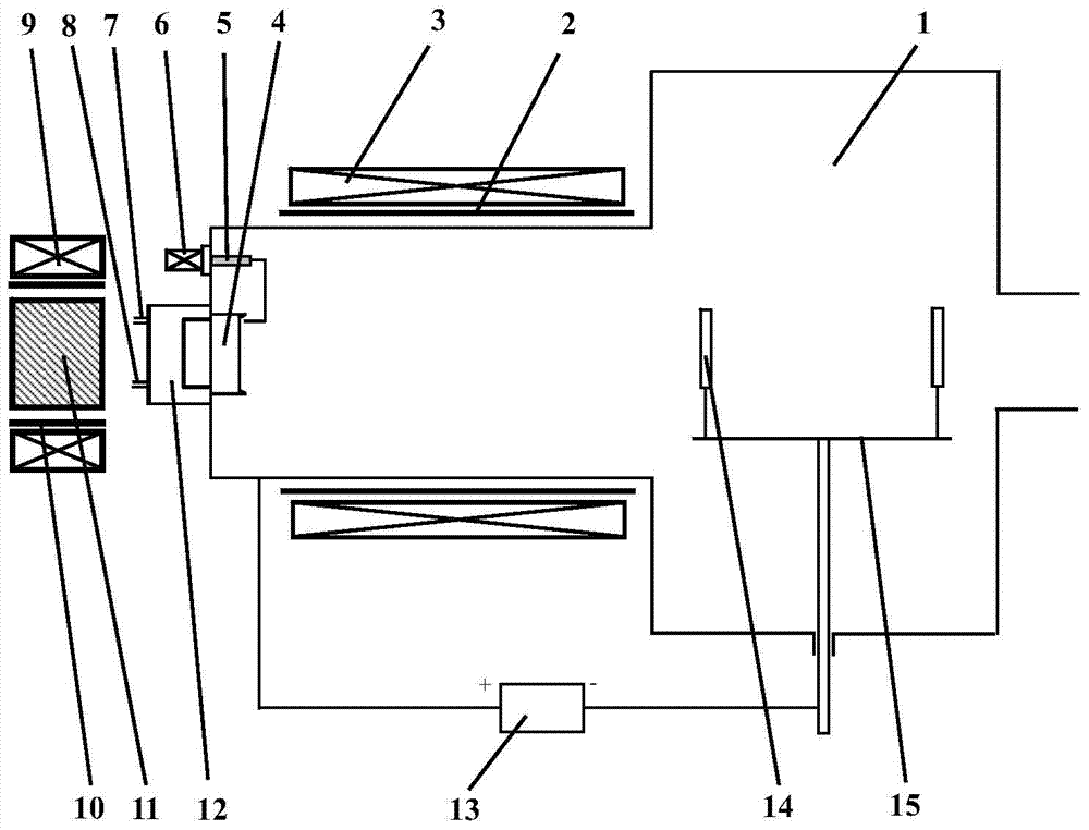
[0028] In this embodiment, the arc ion coating device such as figure 1 As shown, the arc ion plating device mainly includes: a vacuum chamber 1, a plasma confinement electromagnetic coil support cylinder 2, a plasma confinement electromagnetic coil 3, a target material 4, an arc strike needle 5, an arc strike coil 6, a water outlet pipe 7, Water inlet pipe 8, arc spot restraining electromagnetic coil 9, arc spot restraining electromagnetic coil support cylinder 10, nickel-plated pure iron 11, water cooling jacket 12, pulse bias power supply 13, workpiece 14, workpiece table 15, etc. The specific structure is as follows:

[0029]One end of the target material 4 extends into the vacuum chamber 1, and the other end of the target material 4 is provided with a water cooling jacket 12, which is connected with a water outlet pipe 7 and a water inlet pipe 8 to form a circulating water cooling structure for the target material 4. One end of the arc starting needle 5 in the vacuum chamb...

Embodiment 2

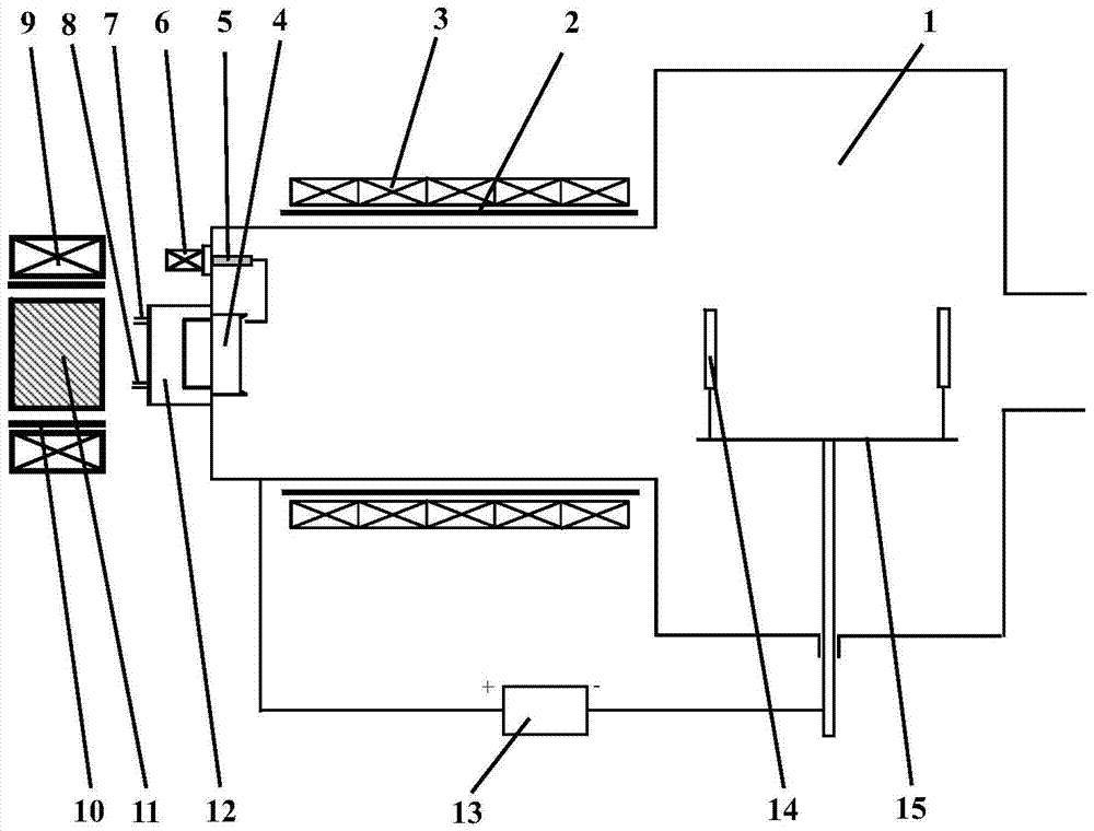
[0034] The difference from Embodiment 1 is that the plasma confinement electromagnetic coil 3 is composed of several electromagnetic coils, the magnetic inductions of these electromagnetic coils are adjusted respectively, and their sizes gradually decrease along the direction of the plasma beam. Its specific deposition device is as figure 2 shown, with figure 1 The difference is that the magnetic field of the workpiece plasma confinement electromagnetic coil 3 in this embodiment adopts a gradient magnetic field. The gradient magnetic field means that the magnetic field generating device placed outside the vacuum chamber on the plasma transmission channel is 4 electromagnetic coils. The wire diameter of the electromagnetic coil, The winding density and other parameters are the same, and the magnetic induction intensity of these electromagnetic coils is realized by adjusting the magnitude of the electromagnetic coil current respectively, and the magnetic induction intensity gra...

Embodiment 3

[0038] This embodiment adopts as figure 1 In the arc ion plating device shown, the substrate is made of cemented carbide (brand YT5), the size of the sample is 20mm×10mm×10mm, and the size of the coating surface is 20mm×10mm. Before coating, the surface of the base material is ground, polished, ultrasonically cleaned and dried, and then placed on the workpiece table in the vacuum chamber. In this embodiment, the target material is a titanium-aluminum (50at.%:50at.%) alloy target. Vacuum until the vacuum degree in the vacuum chamber reaches 5×10 -3 At Pa, argon gas is supplied, the air pressure is controlled at 1.0Pa, the arc spot confinement electromagnetic coil current is adjusted to 3.0A, the plasma confinement electromagnetic coil current is 5.0A, the magnetic induction intensity is 500 Gauss and 800 Gauss respectively, and the workpiece is pulsed with negative bias. -600V, perform glow cleaning on the workpiece for 10 minutes; then, adjust the Ar gas flow rate, adjust th...


PUM

PropertyMeasurementUnit
Thicknessaaaaaaaaaa
Microhardnessaaaaaaaaaa
Thicknessaaaaaaaaaa

Abstract

The invention belongs to the field of surface modification of materials, and particularly relates to a magnetic control arc ion plating composite depositing process and a magnetic control arc ion plating composite depositing device for controlling the movement velocity of a cathode spot, restraining the transmission of plasma, enhancing the deposition rate and deposition uniformity of a thin film, reducing the spraying of large granules positioned on the surface of a target material and enhancing the etching uniformity of the target material. The arc ion plating device is provided with two magnetic field generation devices, one is arranged behind the target material, and the other one is arranged at the outer side of a plasma transmission channel; thin film deposition is accessorily carried out on the surface of a base body through a coupling magnetic field generated by the two magnetic field generation devices. The magnetic control arc ion plating composite depositing process disclosed by the invention can reduce the spraying of the large granules positioned on the surface of the target material and the quantity of the large granules contained in the thin film through the coupling magnetic field generated by the two coupled magnetic field generation devices, thereby solving the problem of nonuniformity of the plasma on a transmission space in the traditional process, enhancing the utilization ratio of the plasma, enhancing the deposition rate of the thin film and the thickness uniformity of the thin film and providing the effective guarantee for preparing various high-property thin films.

Description

Technical field: [0001] The invention belongs to the field of material surface modification, specifically a magnetically controlled arc ion plating composite deposition process and a deposition device, which are used to increase the moving speed of the arc spot, reduce the emission of large particles on the surface of the target material, and improve the deposition rate and deposition uniformity of the film . Background technique: [0002] Arc ion is one of the most widely used physical vapor deposition (PVD) technologies in industry. Due to its high ionization rate, high incident particle energy, good diffraction, and a series of advantages such as low temperature deposition, arc ion plating technology has been obtained. Rapid development and wide application. However, due to the existence of large particles in arc ion plating, the performance and life of coatings and films are seriously affected. Therefore, how to solve the problem of large particles in cathodic arc plat...

Claims


Application Information

Patent Timeline
IPC IPC(8): C23C14/32C23C14/54
Inventor 赵彦辉肖金泉于宝海华伟刚宫骏孙超
Owner INST OF METAL RESEARCH - CHINESE ACAD OF SCI
Learn More