Infusion real-time monitoring instrument for smarter healthcare

A real-time monitoring and intelligent technology, applied in flow monitors, other medical devices, flow control, etc., can solve problems such as patient panic, blood backflow, inability to infuse monitoring, etc., achieve the effect of convenient and safe use, and reduce the cross-sectional area

Inactive Publication Date: 2017-05-24
PINGDINGSHAN UNIVERSITY
10 Cites 4 Cited by

AI-Extracted Technical Summary

Problems solved by technology

[0003] The purpose of the present invention is to provide a real-time monitoring device for infusion used in smart medical treatment, so as to solve the problem in the above-mentioned background technology that if the needle is not pulle...

Abstract

The invention discloses an infusion real-time monitoring instrument for smarter healthcare and belongs to the technical field of smart city. The infusion real-time monitoring instrument comprises a shell, each of the top and the bottom of the shell is provided with a hook, an infusion bag slot is arranged in the cavity of the shell, an infusion bag is arranged in the cavity of the infusion bag slot, a dripping speed sensor is arranged on the inner right wall of the infusion bag slot, a partition is arranged at the inner bottom of the infusion bag slot, an electric telescopic rod is arranged on the right bottom wall of the infusion bag slot, a pressure plate is arranged at the left end of the electric telescopic rod, a display is arranged on the right side of the infusion bag slot, an alarm is arranged at the right top wall of the shell, a switch is arranged at the bottom of the alarm, the top of the infusion bag and the outer wall of a bottom infusion tube is provided with a fixing plate, and the switch is electrically connected with the electric telescopic rod and the dripping speed sensor respectively. The infusion real-time monitoring instrument is convenient and safe in use, real-time response can be performed during infusion, and the alarm is raised when at the end of infusion.

Application Domain

Technology Topic

PediatricsTime response +3

Image

  • Infusion real-time monitoring instrument for smarter healthcare
  • Infusion real-time monitoring instrument for smarter healthcare
  • Infusion real-time monitoring instrument for smarter healthcare

Examples

  • Experimental program(1)

Example Embodiment

[0019] The technical solutions in the embodiments of the present invention will be clearly and completely described below in conjunction with the accompanying drawings in the embodiments of the present invention. Obviously, the described embodiments are only a part of the embodiments of the present invention, rather than all the embodiments. Based on the embodiments of the present invention, all other embodiments obtained by those of ordinary skill in the art without creative work shall fall within the protection scope of the present invention.
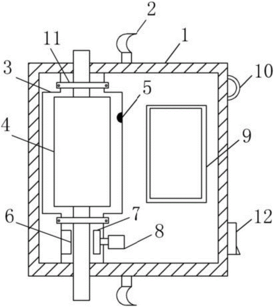
[0020] See Figure 1-7 , The present invention provides a technical solution: a real-time infusion monitoring device for smart medical treatment, comprising a housing 1, the top and bottom of the housing 1 are both provided with hooks 2, and the inner cavity of the housing 1 is provided with a hanging bottle groove 3. The inner cavity of the bottle hanging tank 3 is provided with a hanging bottle 4, the right wall of the inner cavity of the hanging bottle groove 3 is provided with a drip rate sensor 5, the bottom of the inner cavity of the hanging bottle groove 3 is provided with a baffle 6, and the hanging bottle groove 3 An electric telescopic rod 8 is arranged on the right wall of the bottom of the electric telescopic rod 8, a pressure plate 7 is arranged at the left end of the electric telescopic rod 8, the infusion tube at the bottom of the bottle 4 is located between the baffle 6 and the pressure plate 7, and the right side of the bottle tank 3 is provided with a display 9 , The top of the right wall of the housing 1 is provided with an alarm 10, the bottom of the alarm 10 is provided with a switch 12, the top of the bottle 4 and the outer wall of the bottom infusion tube are both provided with a fixing plate 11, and both ends of the fixing plate 11 are screwed Connected to the outer wall of the bottle trough 3, the switch 12 is electrically connected to the electric telescopic rod 8 and the drip speed sensor 5 respectively. The drip speed sensor 5 is electrically connected to the infrared monitoring subsystem 14, and the infrared monitoring subsystem 14 is electrically output. Connected to the central processing unit 13, the central processing unit 13 is connected to the alarm subsystem 15, the display subsystem 16, the wireless communication subsystem 17 and the drip speed adjustment subsystem 18 respectively. The alarm subsystem 15 and the display subsystem 16 are connected to the alarm The device 10 and the display 9 are electrically connected.
[0021] Among them, the infrared monitoring subsystem 14 includes a pulse signal receiving unit 19, the pulse signal receiving unit 19 is electrically connected to the pulse signal processing unit 20, and the pulse signal processing unit 20 is electrically connected to the monitoring processor 21. The monitoring processor 21 is electrically connected. The output is connected to the pulse signal issuing unit 22 and the pulse signal storage unit 23. The alarm subsystem 15 includes a pulse signal conduction unit 24 and a pulse signal interference unit 25. The pulse signal conduction unit 24 and the pulse signal interference unit 25 are both electrically output and connected to the alarm The signal receiving unit 26, the alarm signal receiving unit 26 are electrically connected to the alarm signal processing unit 27, the alarm signal processing unit 27 is electrically connected to the alarm processor 28, and the alarm processor 28 is electrically connected to the alarm signal storage unit 29, and the display sub The system 16 includes the Disu data acquisition unit 30, the Disu data acquisition unit 30 is electrically connected to the Disu data processing unit 31, the Disu data processing unit 31 is electrically connected to the data image processing unit 32, and the data image processing unit 32 is electrically connected. The output is connected to the display processor 33, the display processor 33 is electrically output connected to the data image storage unit 34 and the drive unit 35, the data image storage unit 34 is electrically output connected to the storage interface 36, and the wireless communication subsystem 17 includes an alarm signal acquisition unit 37 , The alarm signal acquisition unit 37 is electrically connected to the wireless receiving unit 38, the wireless receiving unit 38 is electrically connected to the mobile Internet 39, the mobile Internet 39 is electrically output to the wireless communication processor 40, and the wireless communication processor 40 is electrically connected to the The mobile client 41 and the wireless communication storage unit 42, the speed control subsystem 18 includes a speed control information collection unit 43, the speed control information collection unit 43 is electrically connected to the speed control information processing unit 44, and the speed control information processing unit 44 is electrically connected. The output is connected to the speed control information processor 45, and the speed control information processor 45 is electrically output connected to the speed control information storage unit 46 and the electric telescopic rod activation unit 47 respectively.
[0022] Working principle: Turn on the switch 12, the drip speed sensor 5 receives the pulse signal induced by the drip speed sensor 5 through the pulse signal receiving unit 19, and then processes the received pulse signal through the pulse signal processing unit 20 to monitor the processor 21. Through the pulse signal sending unit 22 and the pulse signal storage unit 23, the processed pulse signal is sent and stored. The infrared monitoring subsystem 14 is electrically connected to the central processing unit 13, and the central processing unit 13 is used for data distribution, Sort out, judge and issue instructions. The alarm subsystem 15 receives the pulse signal conduction unit 24 and the pulse signal interference unit 25 through the alarm signal receiving unit 26. When the infusion drops are finished, the pulse signal conduction unit 24 displays the conduction. When the dripping is too fast or too slow, the pulse signal interference unit 25 displays the interference signal, and then the received signal is processed by the alarm signal processing unit 27, and the alarm processor 28 stores the processed signal through the alarm signal storage unit 29 and displays The sub-system 16 includes a drip rate data acquisition unit 30, which can collect the infusion drip rate signal data, the drip rate data processing unit 31 processes the collected data, and the data image processing unit 32 performs image conversion on the processed data. The display processor 33 respectively electrically outputs and connects the data image storage unit 34 and the drive unit 35, and stores the converted image through the data image storage unit 34. The storage interface 36 can move and store the data in the data image storage unit 34. Through the alarm 10 and the display 9, the device performs alarms and displays the infusion drip rate. The wireless communication subsystem 17 includes an alarm signal collection unit 37. The alarm signal collection unit 37 collects the alarm signal, and then the wireless receiving unit 38 and The mobile Internet 39 realizes remote monitoring data transmission, the mobile client 41 remotely understands the situation during the infusion through the wireless communication processor 40, the wireless communication storage unit 42 has the storage of wireless communication data, and the speed adjustment subsystem 18 includes speed adjustment The information collection unit 43 collects the required speed control information, and then the speed control information processing unit 44 processes the collected speed control information, and the speed control information processor 45 respectively electrically outputs the connection speed control information storage unit 46 and the electric telescopic The lever activation unit 47, on the one hand, can store the speed control information, and on the other hand, the electric telescopic lever activation unit 47 activates the movement of the electric telescopic lever 8 to squeeze the infusion tube at the bottom of the sling 4, reducing the infusion in the infusion tube. Area, thereby controlling the speed of dripping.
[0023] Although the embodiments of the present invention have been shown and described, those of ordinary skill in the art can understand that various changes, modifications, and substitutions can be made to these embodiments without departing from the principle and spirit of the present invention. And variations, the scope of the present invention is defined by the appended claims and their equivalents.

PUM

no PUM

Description & Claims & Application Information

We can also present the details of the Description, Claims and Application information to help users get a comprehensive understanding of the technical details of the patent, such as background art, summary of invention, brief description of drawings, description of embodiments, and other original content. On the other hand, users can also determine the specific scope of protection of the technology through the list of claims; as well as understand the changes in the life cycle of the technology with the presentation of the patent timeline. Login to view more.

Similar technology patents

Classification and recommendation of technical efficacy words

  • Reduce the cross-sectional area
  • Easy to use

Electromagnetic valve

Owner:浙江中宝自控元件有限公司

Catheter

Owner:MEDTRONIC PS MEDICAL

Laser assisted total joint arthroplasty

InactiveUS20090234360A1Easy to useNon-surgical orthopedic devicesSurgical sawsLaser assistedLaser guidance
Owner:ALEXANDER VLADIMIR

System, method, and apparatus for settlement for participation in an electric power grid

ActiveUS8583520B1Communication securityEasy to useLevel controlCoin-freed apparatusNetwork managementGrid operator
Owner:CAUSAM ENERGY INC
Why Eureka
Try Eureka