
Positioning method of crosshairs in radiotherapy equipment

A crosshair and radiotherapy technology, which is applied in radiotherapy, treatment, X-ray/γ-ray/particle irradiation therapy, etc., can solve the problems of impreciseness, difficulty in ensuring accuracy, blurred edges of projected images, etc., to achieve accurate images, Improve accuracy and high recognition effect

Active Publication Date: 2019-08-13
SHANGHAI UNITED IMAGING HEALTHCARE
View PDF5 Cites 0 Cited by
  • Summary
  • Abstract
  • Description
  • Claims
  • Application Information

AI Technical Summary

Problems solved by technology

[0008] However, there are many defects in the way that the human eye observes projection coincidence in the prior art
First, the human eye observation is subjective and not accurate; second, the visible light is blurred on the edge of the projected image of the detection plate; third, due to the frequent correction of the crosshairs, it is obvious that the existing correction methods are inconvenient to operate and the accuracy is difficult ensure

Method used


Image

  • Positioning method of crosshairs in radiotherapy equipment
  • Positioning method of crosshairs in radiotherapy equipment
  • Positioning method of crosshairs in radiotherapy equipment

Examples


Embodiment Construction

[0027] The present invention will be further described in detail below in conjunction with the accompanying drawings and embodiments. It should be understood that the specific embodiments described here are only used to explain the present invention, but not to limit the present invention. In addition, it should be noted that, for the convenience of description, only some structures related to the present invention are shown in the drawings but not all structures.

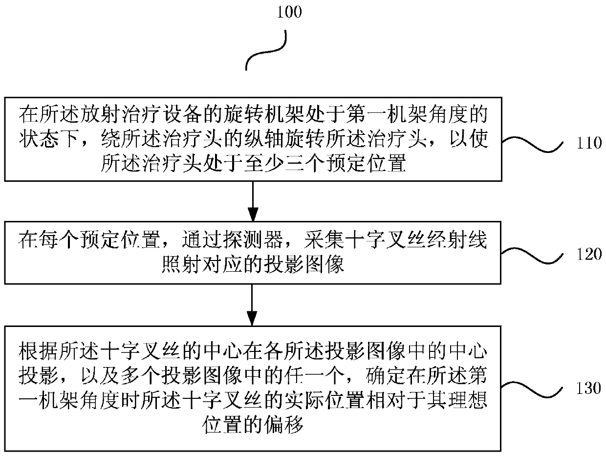
[0028] image 3 It is a flow chart of a method for positioning the crosshairs in radiotherapy equipment provided by an embodiment of the present invention. This embodiment can be applied to positioning the crosshairs in radiotherapy equipment to obtain the installed crosshairs The deviation of the actual position of the crosshair from the ideal position of the crosshair. The method can be implemented by a program, or the method can also be partially implemented by manual operation in cooperation with a control pr...


PUM


Abstract

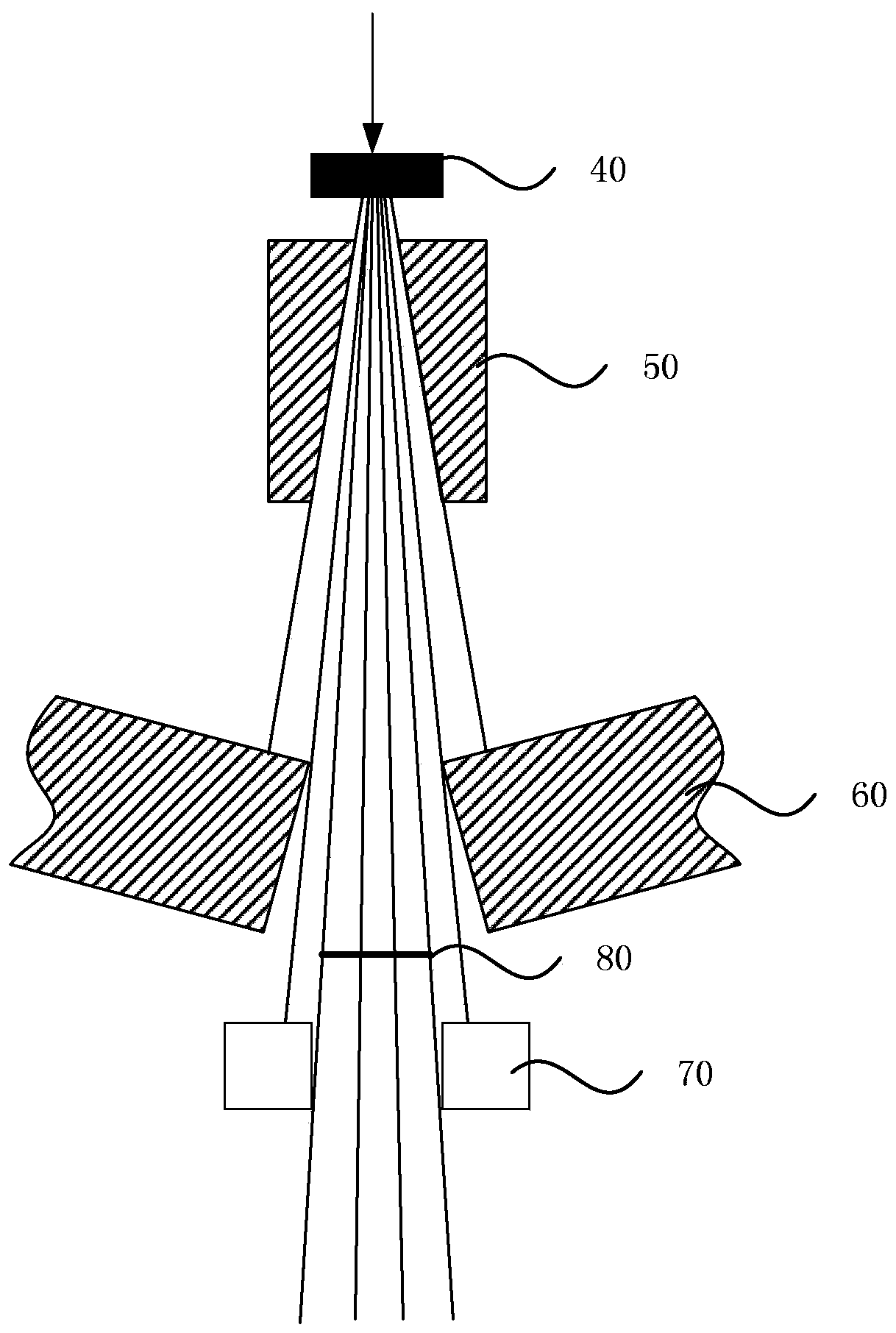
The invention provides a locating method for a cross wire in radiotherapy equipment. The locating method comprises the following steps: when a rotating frame of radiotherapy equipment is at a first frame angle, rotating a treatment head about the longitudinal axis of the treatment head to make the treatment head reach at least three predetermined positions, wherein a cross wire is installed on the ray path in the treatment head; at each predetermined position, acquiring a projected image corresponding to the cross wire irradiated by rays through an image acquisition element; and determining the deviation of the actual position of the cross wire relative to the ideal position thereof at the first frame angle according to the projection of the center of the cross wire in each projected image and any of the multiple projected images. According to the scheme, the position of the cross wire is located by ray projection, the accuracy is higher, and the operation is more convenient.

Description

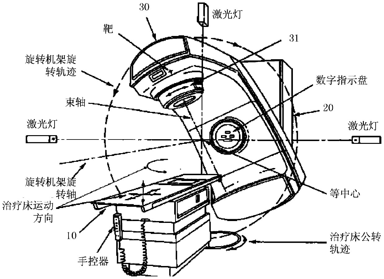
technical field [0001] The invention relates to the field of radiotherapy positioning, in particular to a positioning method for a crosshair in radiotherapy equipment. Background technique [0002] Collimation components are commonly used devices in existing radiation equipment. Typically, collimation components are used in X-ray-based therapeutic instruments to form X-ray radiation fields. [0003] Such as figure 1 Shown is the basic structure of a radiotherapy equipment in the prior art, which mainly includes a treatment couch 10 , a fixed frame 20 and a rotating frame 30 . Rotating frame 30 links to each other with fixed frame 20, as figure 1 As shown, it can be rotated as a whole around the horizontal axis of the fixed frame 20 . The treatment heads 31 in the rotating gantry 30 are independently rotatable about the longitudinal axis of the fixed gantry 20 . The treatment couch 10 can also move in parallel and rotate. The above-mentioned relative movement is to enabl...

Claims


Application Information

Patent Timeline
Patent Type & Authority Patents(China)
IPC IPC(8): A61N5/10
CPCA61N5/1001A61N5/1048A61N5/1077A61N2005/1054A61N2005/1056A61N2005/1092
Inventor 杨宏成朱建伟
Owner SHANGHAI UNITED IMAGING HEALTHCARE
Learn More