
a cutting machine

A cutting machine and body technology, applied in shearing devices, metal processing equipment, manufacturing tools, etc., can solve the problems of blockage, thin wire breakage, bullet injury, etc., to facilitate installation and use, improve cutting accuracy, and improve safety. performance effect

Inactive Publication Date: 2018-03-23
振石集团盛石新材料有限公司
View PDF7 Cites 0 Cited by
  • Summary
  • Abstract
  • Description
  • Claims
  • Application Information

AI Technical Summary

Problems solved by technology

This kind of cutting machine can automatically stop cutting when it reaches the cutting line position to improve cutting accuracy, but this invention has the following problems: 1. When the cutting piece of the cutting machine cuts to a thin line, the thin line will break and hurt people; 2. When the thin wire is broken, the thin wire is easy to be inserted into the workpiece, causing blockage and affecting the normal use of the workpiece

Method used


Image

  • a cutting machine
  • a cutting machine

Examples


Embodiment Construction

[0015] The present invention will be described in further detail below by means of specific embodiments:

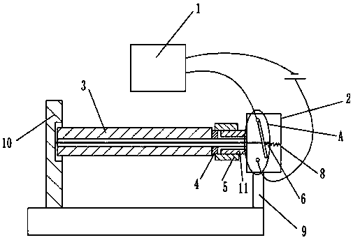
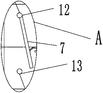
[0016] The reference signs in the drawings of the description include: cutting machine body 1, control box 2, paraffin plate 3, metal sleeve 4, rotating cover 5, hook 6, connecting rod 7, spring 8, first bracket 9, second bracket 10 , Hollow shaft sleeve 11, negative contact point 12, positive contact point 13.

[0017] The embodiment is basically as attached figure 1 Shown: a cutting machine, including a cutting machine body 1, a first bracket 9, and a second bracket 10, the first bracket 9 is provided with a control box 2, the cutting machine body 1 has a cutting sheet, and the control box 2 is provided with a switch , the switch is connected in series with the cutting machine body 1, a paraffin plate 3 is provided between the first support 9 and the second support 10, a cavity is provided in the second support 10, the left end of the paraffin plate 3 extends into the ...


PUM


Abstract

The invention belongs to the field of cutting mechanical devices, and specifically discloses a cutter which comprises a cutter body, a first bracket and a second bracket, wherein a control box is arranged on the first bracket; a switch is arranged in the control box; the switch is in series connected with the cutter body; a paraffin plate is arranged between the first bracket and the second bracket; a cavity is formed in the second bracket; one end of the paraffin plate extends into the cavity; the other end of the paraffin plate is equipped with a metal sleeve; the metal sleeve is rotatably connected with a rotary cover; the rotary cover is rotatably connected with a hollow shaft sleeve; the hollow shaft sleeve is fixedly connected on the control box; a through hole is formed in the paraffin plate; the metal plate sleeve, the rotary cover and the hollow shaft sleeve penetrate through the through hole; an insulated wire is arranged in the through hole; one end of the insulated wire is fixedly connected on the second bracket; and the other end of the insulated wire is connected with the switch. According to the scheme adopted by the invention, the invention provides the cutter which has a safe function, and does not affect normal use of workpieces.

Description

technical field [0001] The invention relates to the field of cutting mechanisms. Background technique [0002] As a cutting tool, the traditional cutting machine has a wide range of applications and can be used to cut many metal or non-metal materials. When cutting, the worker generally draws a cutting line on the workpiece to be cut, and then cuts. The worker Use the naked eye to see that the cutting piece has probably reached the cutting line, and then cut off the power to stop cutting. This method is not only inconvenient to observe but also has low precision. [0003] Chinese invention patent application number CN20 1210569247.6 provides a cutting machine, which includes a cutting machine body and a switch. The switch is connected in series with the cutting machine body. The switch is closed, and the switch is automatically disconnected when the thin wire is disconnected. This kind of cutting machine can automatically stop cutting when it reaches the cutting line posit...

Claims


Application Information

Patent Timeline
Patent Type & Authority Patents(China)
IPC IPC(8): B23D33/10
CPCB23D33/10
Inventor 唐正权
Owner 振石集团盛石新材料有限公司
Learn More