
Material taking machine

A technology of reclaimer and cylinder, which is applied in metal processing and other directions, can solve the problems of poor practicability, dislocation, and narrow application range of reclaimers, and achieve the effect of increasing flexibility and practicability

Inactive Publication Date: 2017-05-24
HONG FU JIN PRECISION IND (SHENZHEN) CO LTD +1
View PDF6 Cites 3 Cited by
  • Summary
  • Abstract
  • Description
  • Claims
  • Application Information

AI Technical Summary

Problems solved by technology

When the interval between the product on the material belt and the product holding area on the carrier belt is not equal, because the distance between the suction cups of the existing reclaimer is fixed, when the reclaimer sucks the product from the material belt and then transposes When it reaches the carrier tape, the product will be misaligned with the product holding area on the carrier tape, and the product cannot be smoothly transferred from the material tape to the carrier tape for packaging, making the existing reclaimer poor in practicability and limited in scope of application. narrow

Method used


Image

  • Material taking machine
  • Material taking machine
  • Material taking machine

Examples


Embodiment Construction

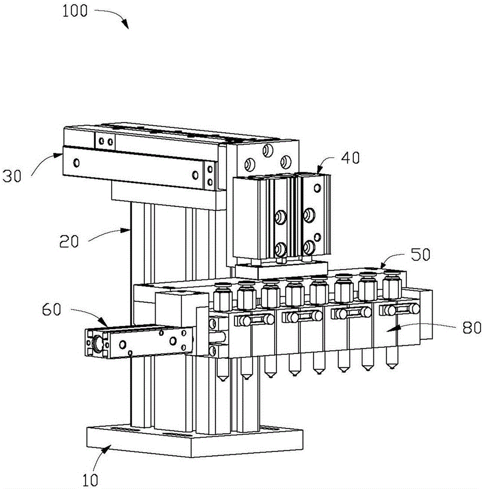
[0015] Such as figure 1 As shown, the reclaimer 100 in one embodiment of the present invention is used to suck products from the material tape and transfer the products to the carrier tape for packaging.

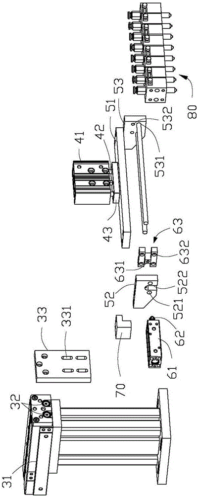
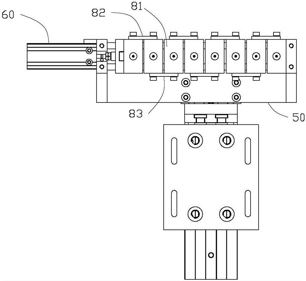
[0016] The reclaimer 100 includes a base 10, a rectangular support portion 20 extending vertically upward from the top of the base 10, a first cylinder 30 connected to the end of the support portion 20 away from the base 10, and The first cylinder 30 is fixedly connected to a second cylinder 40 , a connecting plate 50 connected to the second cylinder 40 , and a third cylinder 60 and nozzle module 80 fixed on the connecting plate 50 .

[0017] The base 10 and the supporting part 20 are rectangles with different sizes. The base 10 and the supporting part 20 can be integrally formed, or the supporting part 20 can be locked on the base 10 by screws. The supporting portion 20 is formed in the middle of the top of the base 10 .

[0018] Please also refer to figure 2 , the fir...


PUM


Abstract

The invention provides a material taking machine. The material taking machine comprises a first cylinder, a second cylinder connected with the first cylinder, a connecting plate connected with the second cylinder and a suction nozzle module located on the connecting plate, wherein the first cylinder and the second cylinder drive the connecting plate and the suction nozzle module to move front and back in the horizontal direction and move up and down in the vertical direction respectively; the material taking machine further comprises a third cylinder fixedly connected with the connecting plate; the suction nozzle module comprises multiple suction nozzles connected through limiting blocks; the third cylinder drives the suction nozzle module to move and adjusts relative intervals between the adjacent suction nozzles; the limiting blocks can drive the adjacent suction nozzles to move and further limit the movement range of each suction nozzle.

Description

technical field [0001] The invention relates to a production and processing equipment, in particular to a production reclaimer. Background technique [0002] In the processing and production of components of electronic products such as mobile phones and tablet computers, the tape is first punched out through the mold, then the product is cut out by the cutting machine, and finally the product is transferred to the packaging tape by the reclaimer for packaging. [0003] The reclaimer drives the suction cup through the cylinder to transfer the product from the material belt to the carrier belt for packaging. The suction cup and the suction cup base of the existing reclaimer are fixed together, and the interval between the suction cups cannot be changed after the suction cup absorbs the product. However, the types of electronic components are different, and the size of the gap between products is often different after the tape is punched out through the mold, while the carrier...

Claims


Application Information

Patent Timeline
IPC IPC(8): B23Q7/04
Inventor 郭化蒋太军董晓利
Owner HONG FU JIN PRECISION IND (SHENZHEN) CO LTD
Learn More