
Construction device for bundling at joints of construction bars
A technology for building steel bars and construction devices, which is applied in the field of wire binding hooks, can solve the problems of inconvenient penetration into the interior of steel bars, difficulty in binding steel bars, and inconvenience in use, so as to improve practicability and flexibility, and improve flexibility and practicability , easy to use and flexible effects
- Summary
- Abstract
- Description
- Claims
- Application Information
AI Technical Summary
Problems solved by technology
Method used
Image

Examples
Embodiment
[0034] as attached figure 1 To attach Figure 8 Shown:
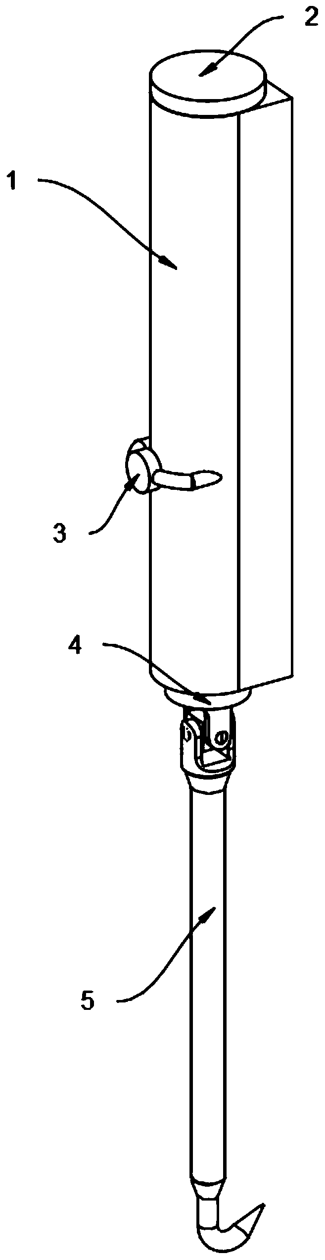
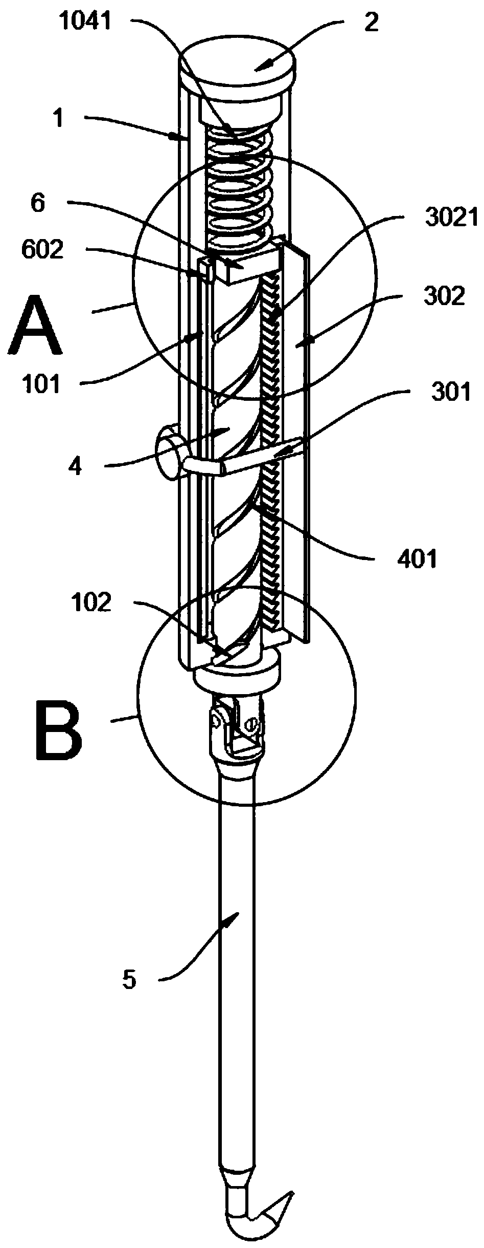
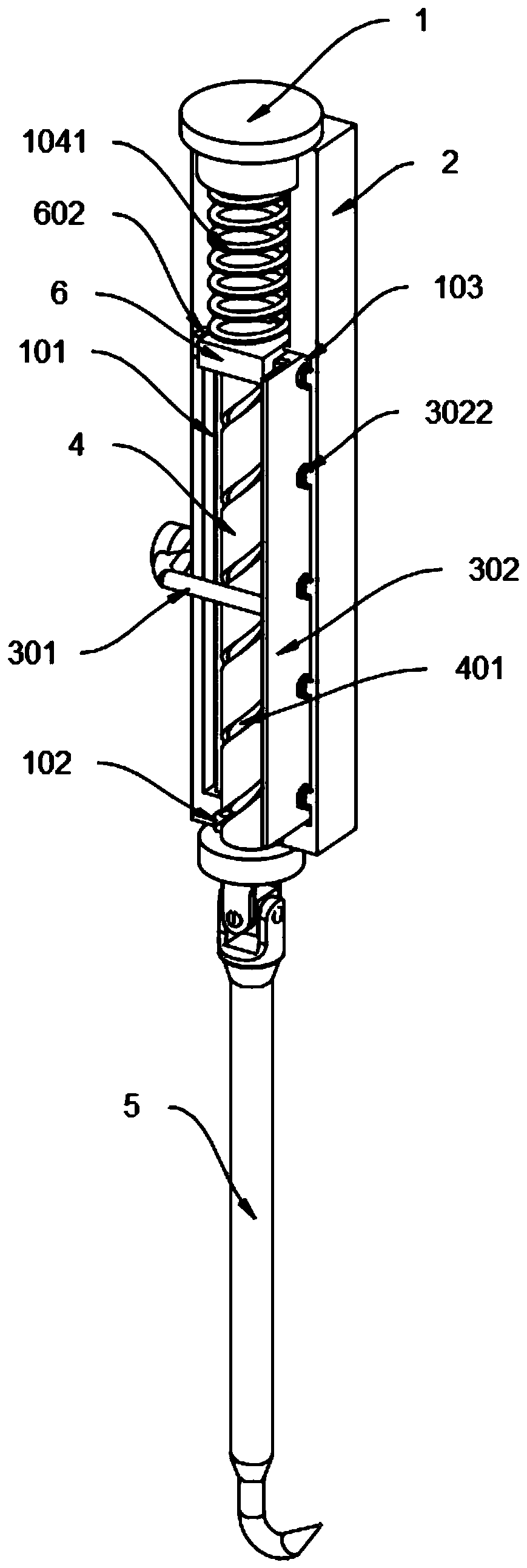
[0035] The invention provides a construction device for bundling at the intersection of building steel bars, which includes a holding tube 1, a sealing cap 2, a reset mechanism 3, a rotating rod 4 and a binding rod 5; The plate 302 can move back and forth in the movable groove 103. The back of the reset plate 302 is provided with a top spring 3022, and the two ends of the top spring 3022 are respectively fixedly connected to the inside of the reset plate 302 and the side of the holding tube 1. image 3 , attached Figure 4 , attached Figure 5 And attached Figure 8 As shown, the reset plate 302 can be reset under the action of the top spring 3022 after the reset linkage lever 301 is released in this design, so as to prepare for the next binding of steel bars, which improves the flexibility of the device; the top surface of the holding tube 1 is provided with Spring barrel 104, and the diameter of spring barrel 104 ...
PUM
 Abstract
Description
Claims
Application Information