Spiral yarn printing and dyeing equipment

A kind of printing and dyeing equipment, spiral technology, applied in the field of spiral yarn printing and dyeing equipment, can solve the problems of difference in dyeing effect, increase dyeing cost, shorten delivery cycle, etc., to speed up efficiency, reduce dyeing and printing cost, and ensure dyeing consistent effect

Active Publication Date: 2017-05-24
海宁鑫港源纺织品有限公司
View PDF3 Cites 11 Cited by
  • Summary
  • Abstract
  • Description
  • Claims
  • Application Information

AI Technical Summary

Problems solved by technology

[0002] With the development of the times, the food, clothing, housing and transportation that must be satisfied in life are also constantly developing and innovating. As textiles that are necessary for clothing, yarn is the basic material. In the production process of textiles, the stage of dyeing is affected by several factors. Influence, from an economic point of view, dyeing is carried out at the front of the weaving production process, and its cost is the lowest. If the yarn is dyed before weaving, dyes with better fastness can be selected, and the delivery cycle can be shortened. , so yarn dyeing is widely used by people, and most of the existing yarn dyeing methods use the method of yarn soaking to directly contact the yarn with the pigment, which will cause differences in the dyeing effect due to uneven soaking, making Distinct lengths, color segments of different sizes, color spots and other problems are presented, and at the same time, it also causes a lot of waste of pigments and increases the dyeing cost. Therefore, it is necessary to improve the existing yarn dyeing machine to solve the above problems

Method used


Image

  • Spiral yarn printing and dyeing equipment
  • Spiral yarn printing and dyeing equipment
  • Spiral yarn printing and dyeing equipment

Examples


Embodiment Construction

[0014] The following will clearly and completely describe the technical solutions in the embodiments of the present invention with reference to the accompanying drawings in the embodiments of the present invention. Obviously, the described embodiments are only some, not all, embodiments of the present invention. Based on the embodiments of the present invention, all other embodiments obtained by persons of ordinary skill in the art without making creative efforts belong to the protection scope of the present invention.

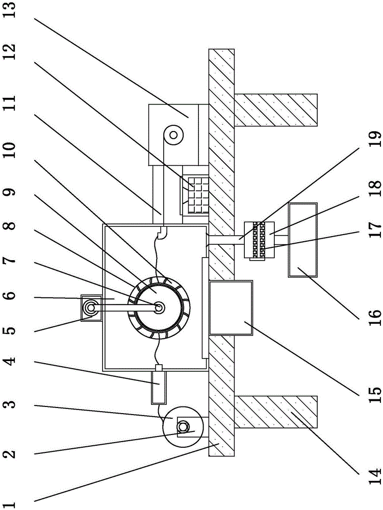
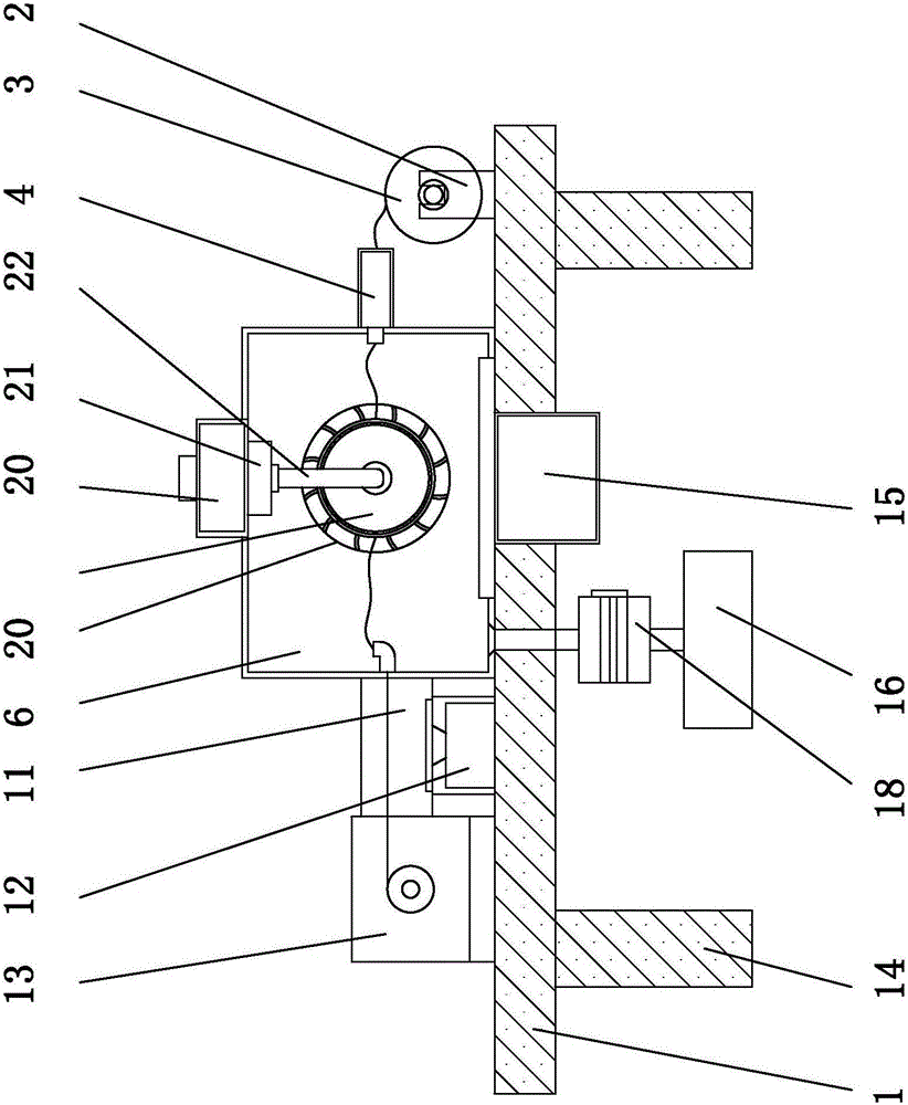
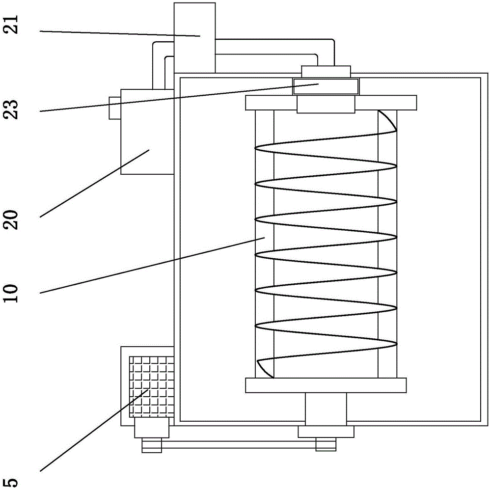
[0015] see Figure 1-3 , an embodiment provided by the present invention: a spiral yarn printing and dyeing equipment, including a base 1, a discharge roller 3, a dyeing and printing chamber 6, a drying chamber 11 and a paint box 20, both ends of the bottom of the base 1 are installed There is a support column 14, a dyeing and printing room 6 is arranged in the middle above the base 1, and an electric heater 15 is installed on the base 1 at the bottom of the d...


PUM


Abstract

The invention discloses spiral yarn printing and dyeing equipment which comprises a base, a discharge roller, a dyeing and printing chamber, a drying chamber and a pigment tank. The two ends of the bottom of the base are each provided with a support column, a yarn discharge device is installed at a feed inlet formed in the side, close to a discharge base, of the dyeing and printing chamber, the output end of a booster pump is connected with a pigment ejection pipe through a pigment guide pipe, and a bearing structure is installed on the inner side wall of the portion, at the joint of the pigment guide pipe and the pigment ejection pipe, of the dyeing and printing chamber. According to the spiral yarn printing and dyeing equipment, yarn can be spirally wound on a dyeing and printing roller to be dyed through an arranged dyeing and printing roller with a spiral yarn groove, the dyeing time is prolonged, the dyeing uniformity is guaranteed, and the phenomenon that color segments and color points with different lengths and sizes are generated is avoided; meanwhile, pigments can be saved by means of the pigment ejection pipe arranged in the dyeing and printing roller on the premise that the yarn is fully dyed and are greatly saved by cooperating with usage of a pigment recycle tank, the dyeing and printing cost is reduced, and meanwhile the dyeing and printing quality and the yarn dyeing and printing production efficiency are improved.

Description

technical field [0001] The invention relates to the field of yarn dyeing equipment, in particular to a spiral yarn printing and dyeing equipment. Background technique [0002] With the development of the times, the food, clothing, housing and transportation that must be satisfied in life are also constantly developing and innovating. As textiles that are necessary for clothing, yarn is the basic material. In the production process of textiles, the stage of dyeing is affected by several factors. Influence, from an economic point of view, dyeing is carried out in the front of the weaving production process, and its cost is the lowest. If the yarn is dyed before weaving, dyes with better fastness can be selected, and the delivery cycle can be shortened. , so yarn dyeing is widely used by people, and most of the existing yarn dyeing methods use the method of yarn soaking to directly contact the yarn with the pigment, which will cause differences in the dyeing effect due to uneve...

Claims


Application Information

Patent Timeline
Patent Type & Authority Applications(China)
IPC IPC(8): D06B1/14D06B23/02D06B23/20D06B23/22D06B15/00
CPCD06B1/142D06B15/00D06B23/026D06B23/20D06B23/22
Inventor 杨建良
Owner 海宁鑫港源纺织品有限公司
Why Eureka
Try Eureka