Air intake duct lip deformation structure and air intake duct lip deformation structure control method

A technology of deformation structure and control method, which is applied in the direction of jet propulsion device, gas turbine device, machine/engine, etc., to achieve the effect of excellent propulsion matching characteristics and excellent aerodynamic performance

Active Publication Date: 2017-05-24
SHENYANG AIRCRAFT DESIGN INST AVIATION IND CORP OF CHINA
View PDF6 Cites 6 Cited by
  • Summary
  • Abstract
  • Description
  • Claims
  • Application Information

AI Technical Summary

Problems solved by technology

[0003] The purpose of the present invention is to provide a deformation structure of the intake port lip and a control method for the deformation structure of the intake port lip, so as to solve or at least alleviate at least one problem existing in the background technology

Method used


Image

  • Air intake duct lip deformation structure and air intake duct lip deformation structure control method
  • Air intake duct lip deformation structure and air intake duct lip deformation structure control method
  • Air intake duct lip deformation structure and air intake duct lip deformation structure control method

Examples


Embodiment Construction

[0028] In order to make the objectives, technical solutions and advantages of the present invention clearer, the technical solutions in the embodiments of the present invention will be described in more detail below in conjunction with the drawings in the embodiments of the present invention. In the drawings, the same or similar reference numerals denote the same or similar elements or elements having the same or similar functions throughout. The described embodiments are some, but not all, embodiments of the invention. The embodiments described below by referring to the figures are exemplary and are intended to explain the present invention and should not be construed as limiting the present invention. Based on the embodiments of the present invention, all other embodiments obtained by persons of ordinary skill in the art without creative efforts fall within the protection scope of the present invention. Embodiments of the present invention will be described in detail below ...


PUM


Abstract

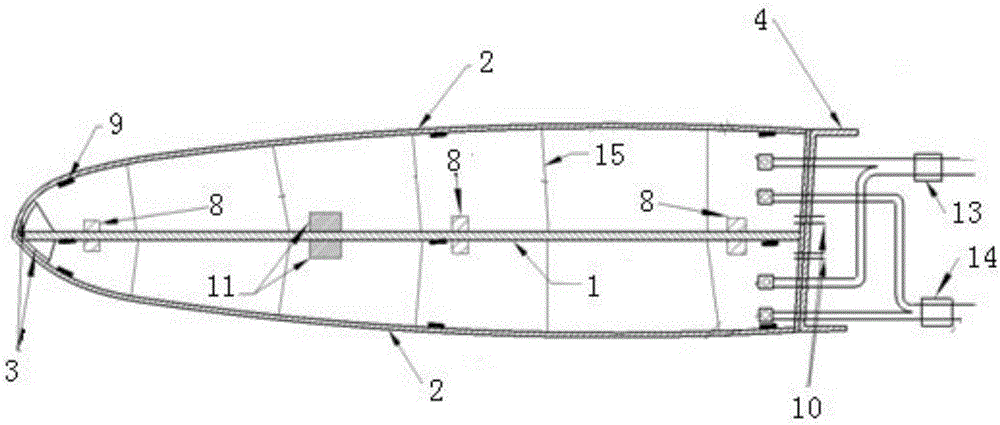
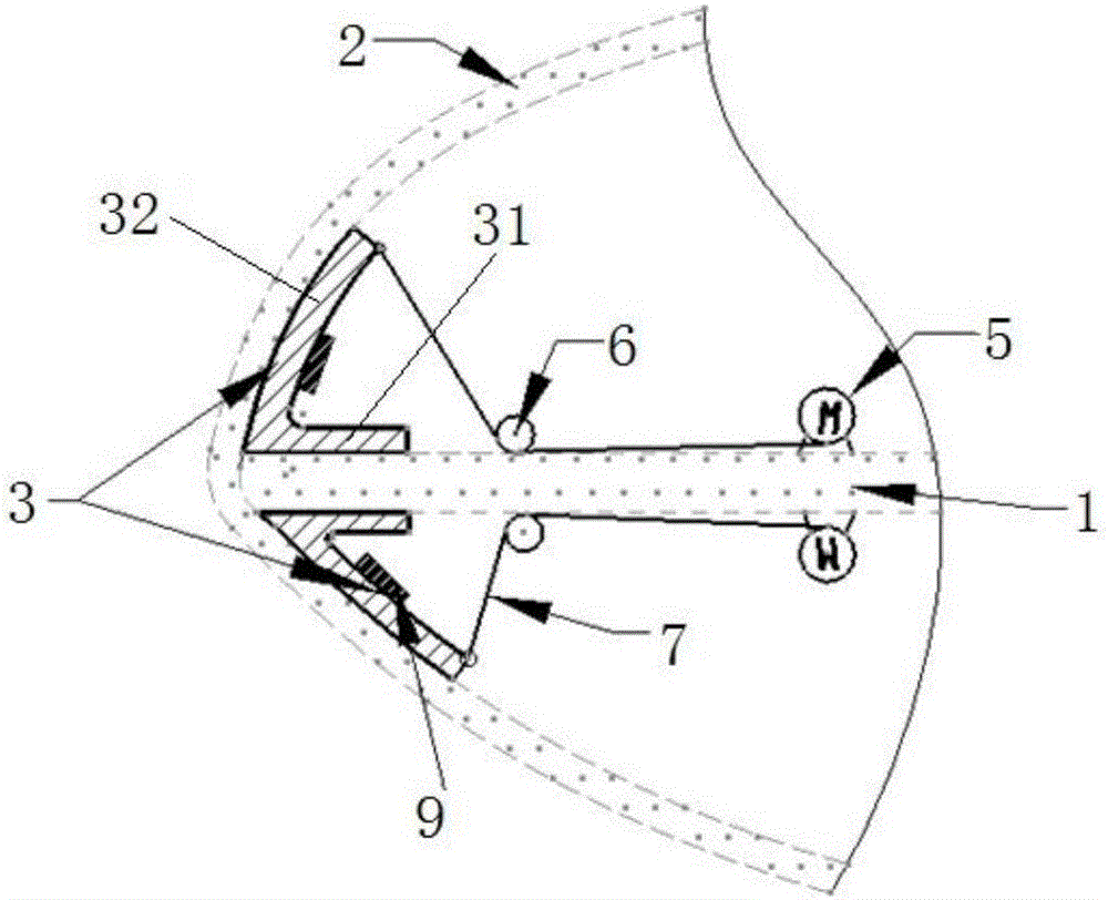
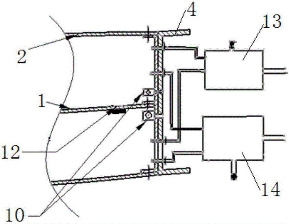
The invention discloses an air intake duct lip deformation structure and an air intake duct lip deformation structure control method. The air intake duct lip deformation structure comprises a main bearing structure, a skin, a lip margin structure, temperature sensors, a plurality of strain sensors, a temperature adjustment device and a lip margin structure driving device. The main bearing structure is made of a memory alloy material, and is arranged in an enclosed cavity formed by the skin; the enclosed cavity is equipped with an air inlet and an air outlet; the temperature adjustment device is connected to the air inlet of the enclosed cavity; the temperature sensors are arranged on the main bearing structure; the strain sensors are arranged on the inner surface of the skin and the main bearing structure; and the lip margin structure driving device is arranged on the main bearing structure. The air intake duct lip deformation structure control method mainly utilizes the air intake duct lip deformation structure to realize control. According to the invention, the shape of the air intake duct lip can be changed repeatedly within certain range according to actual flying speed.

Description

technical field [0001] The invention relates to the technical field of aeronautical structure design, in particular to an intake port lip deformation structure and a control method for the intake port lip deformation structure. Background technique [0002] For an aircraft whose maximum flight M number is supersonic, the matching problem of the intake port / engine is always a thorny problem. From stationary to take-off state, the incoming flow velocity gradually increases from zero. Because the incoming flow velocity is very low, the airflow entering the air intake will be sucked in from the surrounding environment, causing the airflow in the air intake to separate, and the lip of the air intake will The thinner it is, the more serious the separation of the airflow will be, resulting in the blockage of the inlet throat, the distortion of the flow field at the inlet of the engine, the increase of the total pressure loss, the increase of the thrust loss, and the increase of the...

Claims


Application Information

Patent Timeline
Patent Type & Authority Applications(China)
IPC IPC(8): F02C7/042F02C7/057
CPCF02C7/042F02C7/057
Inventor 邱涛靳诚忠单兴业田智亮张鹤
Owner SHENYANG AIRCRAFT DESIGN INST AVIATION IND CORP OF CHINA
Why Eureka
Try Eureka