Blade

A blade and leading edge technology, applied in the field of blades, can solve the problems of large vortex shedding noise at the trailing edge of the blade, serious flow separation on the blade surface, affecting the blade efficiency, etc., to reduce the turbulence intensity, reduce the shedding noise, and improve the blade efficiency.

Inactive Publication Date: 2017-05-24
JOHNSON CONTROLS BUILDING EFFICIENCY TECH WUXI +2
View PDF5 Cites 6 Cited by
  • Summary
  • Abstract
  • Description
  • Claims
  • Application Information

AI Technical Summary

Problems solved by technology

However, the leading edge 12 and the trailing edge 11 are both straight lines along the span direction, and the flow separation on the blade surface is serious, which affects the efficiency of the blade, and the noise of vortex shedding at the trailing edge of the blade is relatively large

Method used


Image

  • Blade
  • Blade
  • Blade

Examples


Embodiment Construction

[0026] In the following description, numerous specific details are given in order to provide a more thorough understanding of the present invention. It will be apparent, however, to one skilled in the art that embodiments of the invention may be practiced without one or more of these details. In other examples, some technical features known in the art are not described in order to avoid confusion with the embodiments of the present invention.

[0027] In order to thoroughly understand the embodiments of the present invention, a detailed structure will be set forth in the following description. It is evident that practice of the embodiments of the invention is not limited to specific details familiar to those skilled in the art. Preferred embodiments of the present invention are described in detail below, however, the present invention may have other embodiments besides these detailed descriptions.

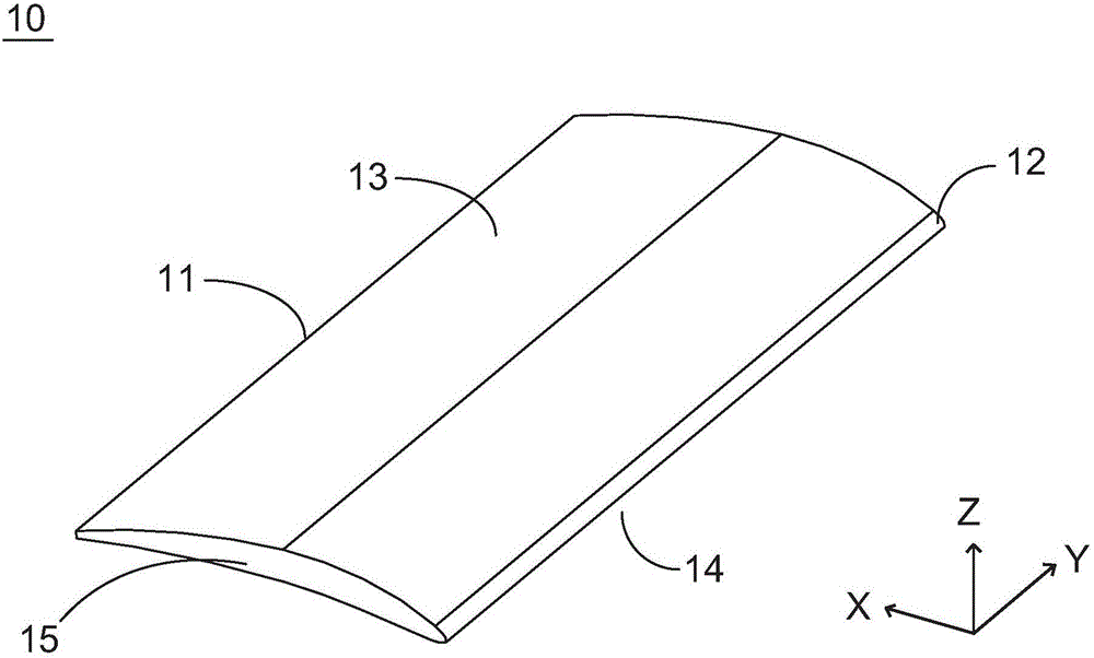
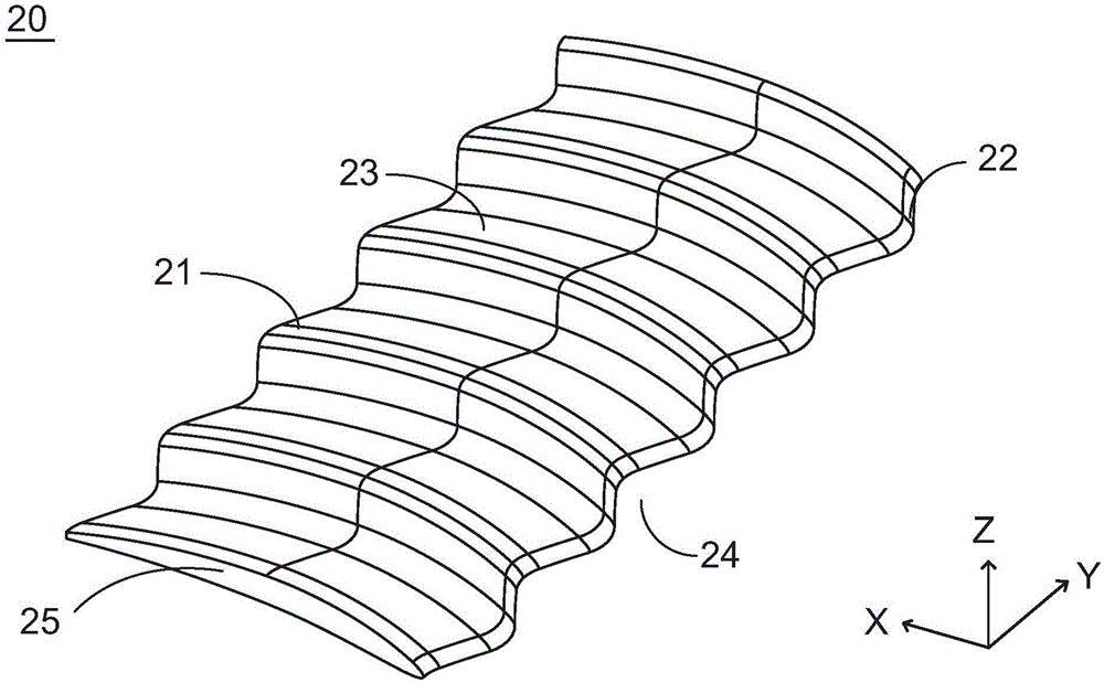
[0028] Such as figure 2 As shown, the present invention discloses a blade ...


PUM


Abstract

The invention provides a blade. The blade comprises a leading edge allowing a liquid to flow in, a tailing edge allowing the liquid to flow out, a suction surface and a pressure surface, wherein one end of the edge of the suction surface is connected with one end of the edge of the pressure surface at the leading edge, the other end of the edge of the suction surface is connected with the other end of the edge of the pressure surface at the tailing edge, shapes of aerofoil sections of the blade in the extending direction keep unchanged, and positions of leading and tailing edges of center lines of the aerofoil sections of the blade are periodically distributed in the extending direction. The positions of the leading and tailing edges of the center lines of the aerofoil sections of the blade are periodically distributed in the extending direction, so that flow separation on the blade surface can be effectively inhibited, turbulence intensity of the tailing edge is reduced, efficiency of the blade is improved, and falling-off noise of tailing edge vortex is reduced.

Description

technical field [0001] The invention relates to the field of rotary machines, in particular to a blade applied to various rotary machines. Background technique [0002] Generally, various rotating machines such as centrifugal compressors, pumps, and fan impellers are composed of different numbers of blades arranged at intervals in the circumferential direction, and the blades are generated by the basic airfoil along the span direction (axial direction). The blade has a leading edge into which fluid flows and a trailing edge from which fluid exits, as well as a concave pressure surface and a convex suction surface. The efficiency of the blade itself has an important impact on the efficiency and noise of rotating machinery such as centrifugal compressors, pumps and fans. Conventional blades 10 such as figure 1 As shown, it has a pressure side 14 and a suction side 13 . The basic airfoil is a straight blade formed by the airfoil section 15 along the span direction, and the b...

Claims


Application Information

Patent Timeline
IPC IPC(8): F04D29/30F04D29/38
Inventor 吴成刚王利
Owner JOHNSON CONTROLS BUILDING EFFICIENCY TECH WUXI
Why Eureka
Try Eureka