A multi-hole wind turbine energy booster

A technology of wind turbines and holes, which is applied to wind turbines, wind turbines consistent with the wind direction, and wind power generation. It can solve the problems of large pressure difference between the upstream and downstream of the deflector, ineffective air speed-up effect, and wind turbine power drop. and other problems, to achieve the effect of increasing output power, simple structure, and reducing load fluctuations

Active Publication Date: 2019-08-06
HOHAI UNIV
View PDF1 Cites 3 Cited by
  • Summary
  • Abstract
  • Description
  • Claims
  • Application Information

AI Technical Summary

Problems solved by technology

However, this energizer has the following disadvantages: 1) Both the deflector plate and the ground have an inclination angle. On the one hand, the effective wind-shielding area is small, and the effect on the acceleration of the upper air is not obvious. On the other hand, it is easy to cause vertical load fluctuations; 2. ) The deflector is an airtight solid structure. On the one hand, the pressure difference between the upstream and downstream of the deflector will be large, and on the other hand, a high shear layer will be formed between the rear of the deflector and the bottom of the wind turbine; 3) Surrounding layout In , the deflector behind the plane of rotation of the wind turbine will cause the power of the wind turbine to drop

Method used


Image

  • A multi-hole wind turbine energy booster
  • A multi-hole wind turbine energy booster
  • A multi-hole wind turbine energy booster

Examples


Embodiment 1

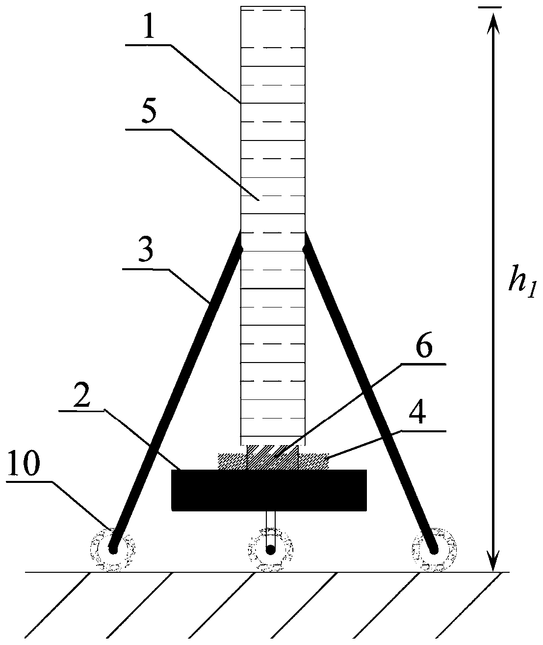
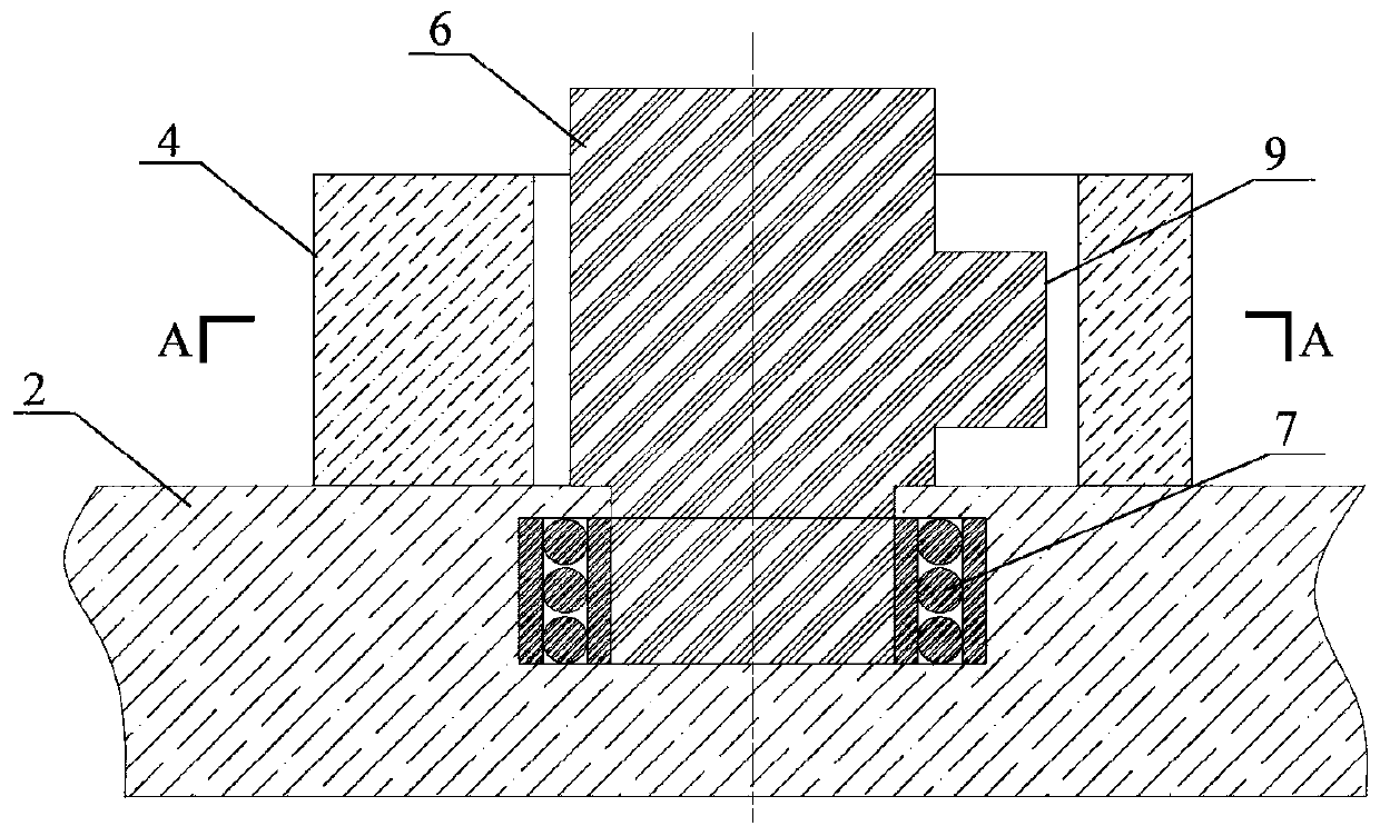
[0042] According to the above-mentioned design scheme of the present invention, in combination Figure 5 and Figure 6 , taking a horizontal axis wind turbine with a radius of 4.5m and a hub height of 8.3m as an example: a mobile porous deflector arrangement is adopted, the deflector length is 11.2m, the height is 1.8m, and the porosity is 35%. The seat length is 11.7m, the distance between the deflector and the wind turbine rotation plane is 8.3m, the damping limit device uses 6 springs, and 6 sets of brackets.

Embodiment 2

[0044] According to the above-mentioned design scheme of the present invention, in combination Figure 7 , taking a model wind turbine with a radius of 6cm and a hub height of 12.5cm as an example: the fixed porous deflector layout is adopted, and the base, main shaft and damping limit device are not required. The porous deflector is directly built on the ground surface, and the porous deflector The height of the deflector is 1.2cm, the thickness is 0.4cm, the porosity is 15%, the distance between the porous deflector and the rotation plane of the wind turbine is 6cm, and the wind speed at the wind speed of 4.0, 5.3, 7.5 and 9.3m / s In the hole test, the output power growth rate of the model wind turbines is above 5%.

Embodiment 3

[0046] According to the above-mentioned design scheme of the present invention, in Figures 5 to 6 or Figure 7 based on combining Figure 8 , the arc-type porous deflector is used instead of the straight-plate porous deflector. The deflector is arranged symmetrically with respect to the center line of the wind turbine shaft. The included angle α between the line and the rotation plane of the wind turbine is 0-60 degrees.

[0047] According to the actual situation, in another specific implementation according to the present invention, trees (such as pine trees, etc.) with suitable height and strong branches are directly planted in front of the wind turbine, so as to realize the win-win situation of resource development and vegetation greening.

[0048] In a specific implementation process, the thickness and material of the porous deflector, the material of the bracket, the width and material of the base, etc. may be determined according to actual conditions.

[0049] The in...


PUM


Abstract

The invention discloses a multi-hole type wind turbine energizer. The multi-hole type wind turbine energizer comprises a multi-hole guide plate with uniformly distributed holes, a pedestal, and a damping limiting device which is arranged between the multi-hole guide plate and the pedestal for buffering or limiting left-right rotation of the multi-hole guide plate, wherein the centre of the multi-hole guide plate is equipped with a main shaft; the multi-hole guide plate is connected with the pedestal through the main shaft and a rolling bearing; and the damping limiting device comprises a damping limiting device body, a plurality of baffle plates and a spring which is arranged between every two adjacent baffle plates. The multi-hole type wind turbine energizer can buffer and limit left-right rotation of the multi-hole guide plate, and the baffle plates are uniformly distributed on the main shaft and the damping limiting device body in a peripheral direction. The multi-hole type wind turbine energizer can efficiently utilize low-speed air energy below a wind turbine, can effectively improve wind turbine output power, also can reduce wind turbine load fluctuation, and can reduce influences of the environment to be smallest.

Description

technical field [0001] The invention relates to the technical field of wind power generation, in particular to a multi-hole wind power booster. Background technique [0002] As a clean and renewable energy, the wind power industry has achieved rapid development in the world. According to the statistics of GWEC, the Global Wind Energy Commission, by the end of 2017, the cumulative installed capacity of wind power in the world was 539GW, of which, the cumulative installed capacity of my country was 188.4GW, and the wind power generation accounted for about 4.8% of the country's electricity consumption. Wind power still has great development prospects, especially in the field of distributed wind power and low wind speed wind power. [0003] Wind turbines usually operate at the bottom of the atmospheric boundary layer, and the bottom atmospheric boundary layer has many unfavorable factors such as large wind shear, low wind speed, and high turbulence intensity. Therefore, in ord...

Claims


Application Information

Patent Timeline
Patent Type & Authority Patents(China)
IPC IPC(8): F03D1/04
CPCF03D1/04Y02E10/72
Inventor 刘惠文郑源张玉全陈会向阚阚付士凤
Owner HOHAI UNIV
Why Eureka
Try Eureka