Unpowered draught fan with support frames as wing-shaped blades

A technology of airfoil blades and support frames, which is applied in the direction of machines/engines, liquid fuel engines, mechanical equipment, etc., can solve the problems of unreasonable fan support frames, small effective aerodynamic area, and high turbulence intensity, so as to improve flow disturbance, Effect of reducing turbulence intensity and reducing noise

Active Publication Date: 2016-07-20
嘉兴笼列电子商务有限公司
View PDF6 Cites 4 Cited by
  • Summary
  • Abstract
  • Description
  • Claims
  • Application Information

AI Technical Summary

Problems solved by technology

[0010] The purpose of the present invention is to solve the current situation that the effective aerodynamic area of ​​the existing non-powered fan is small, the internal support frame of the fan is unreasonable, etc., the resulting internal flow disturbance of the fan is large, the turbulent flow intensity is large, etc., which eventually lead to the problem of low static pressure efficiency, and To solve the problem of noise caused by the vortex area, provide a non-powered fan with optimized flow field parameters, high efficiency, low noise, and airfoil blades as the support frame

Method used


Image

  • Unpowered draught fan with support frames as wing-shaped blades
  • Unpowered draught fan with support frames as wing-shaped blades
  • Unpowered draught fan with support frames as wing-shaped blades

Examples


Embodiment Construction

[0029] The present invention will be further described below in conjunction with accompanying drawing.

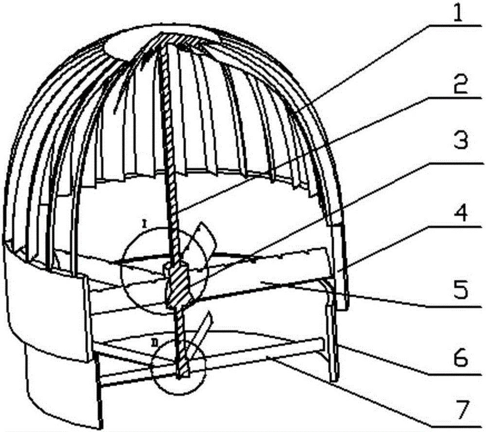
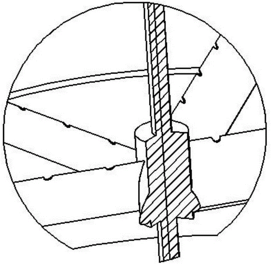
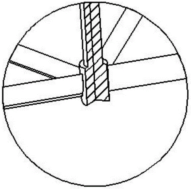
[0030] Such as figure 1 , 2 As shown in and 3, the support frame is a non-powered fan with airfoil blades, which is supported by a wind cutting blade 1, a central shaft 2, a bearing, a positioning sleeve 3, a cylindrical pipe diameter 4, an upper end support frame 5, a variable angle pipe diameter 6, and a lower end support Frame 7 and turbine top plate form. The lower end support frame 7 is a plurality of lower end airfoil blades, one end of the lower end airfoil blade is fixed on the bottom of the central shaft 2, and the other end is fixed on the inner wall of the variable angle pipe diameter 6; the upper end support frame 5 is a plurality of upper end airfoil blades, the upper end wing One end of the type blade is fixed on the positioning sleeve 3, and the other end is fixed on the inner wall of the cylindrical pipe diameter 4; the positioning sleeve 3 is supported on...


PUM


Abstract

The invention discloses an unpowered draught fan with support frames as wing-shaped blades. According to an existing unpowered draught fan, strong vortexes will be formed behind plate support frames, and the turbulence degree of a flow field is intensified. The lower-end support frame of the unpowered draught fan is formed by multiple lower-end wing-shaped blades, one end of each lower-end wing-shaped blade is fixed to the bottom of a center shaft, and the other end of each lower-end wing-shaped blade is fixed to the inner wall of an angle-changing pipe diameter; the upper-end support frame of the unpowered draught fan is formed by multiple upper-end wing-shaped blades, one end of each upper-end wing-shaped blade is fixed to a positioning sleeve, and the other end of each upper-end wing-shaped blade is fixed to the inner wall of a cylinder pipe diameter; the positioning sleeve is supported to the center shaft through a bearing; the chord length of the upper-end wing-shaped blades is larger than the chord length of the lower-end wing-shaped blades; the bottoms of the multiple air cutting blades are welded to the end face of the top of the cylinder pipe diameter, and the tops of the multiple air cutting blades and a turbine top plate are welded; and the top of the center shaft is supported into a bearing hole formed in the turbine top plate through a bearing. By means of the unpowered draught fan, flow disturbance of the flow field in the draught fan is improved, vibration of complex turbulence conditions on the draught fan is weakened, and the service life of the draught fan is prolonged.

Description

technical field [0001] The invention belongs to the field of ventilation equipment and relates to a non-powered fan, in particular to a non-powered fan whose support frame is an airfoil blade and has notches. Background technique [0002] Fan is a general-purpose machine with a wide range of applications, ranging from mine ventilation, boiler draft and chemical process, to industrial furnace blast, air conditioning, and building ventilation. Well-designed, manufactured and rationally used ventilators are of great significance to energy saving and noise pollution reduction. [0003] The non-powered ventilator is a commonly used type in the roof ventilator series, which is mainly used in the top floor of the community, hospitals, restaurants, gymnasiums, large factories and other occasions that require roof ventilation. The unpowered fan uses the natural wind speed to drive the turbine of the fan to rotate, and uses the principle of indoor and outdoor air convection to captur...

Claims


Application Information

Patent Timeline
Patent Type & Authority Applications(China)
IPC IPC(8): F04D29/68F04D29/00
CPCF04D29/002F04D29/681
Inventor 窦华书李昆航陈小平魏义坤杨徽陈兴迟少卿王天垚
Owner 嘉兴笼列电子商务有限公司
Why Eureka
Try Eureka