Side channel compressor

a compressor and side channel technology, applied in the direction of machines/engines, stators, liquid fuel engines, etc., can solve the problem of further reducing the tonal sound components, and achieve the effect of a particularly silent operation

Active Publication Date: 2014-03-04
GARDNER DENVER DEUTLAND
View PDF9 Cites 4 Cited by
  • Summary
  • Abstract
  • Description
  • Claims
  • Application Information

AI Technical Summary

Benefits of technology

[0005]It is the object of the invention to provide a side channel compressor which ensures a particularly silent operation.
[0007]The essence of the invention is that the cross-sectional area of the side channel tapers between the gas inlet opening and the gas outlet opening, with the result that detachments at the edges and at the back of the impeller blades are minimized such that the turbulence intensity in the side channel is reduced considerably. This ensures a particularly silent operation.
[0008]When seen from the gas inlet opening towards the gas outlet opening, the side channel advantageously tapers irregularly; a continuous, in particular linear, decrease in cross-sectional area is not desirable. Said decrease may be strictly monotonic or non-monotonic. In contrast to a monotonic decrease, a non-monotonic decrease is characterized in that the cross-sectional area of the side channel may increase in some regions or may even remain constant. Likewise, the cross-sectional area may also comprise regions that taper more quickly as well as regions that taper less quickly. When the decrease is strictly monotonic, the cross-sectional area does not increase at all but tapers to various degrees. This means that there may be regions that taper more quickly as well as regions that taper less quickly. This prevents formation of regular harmonic flow structures and ultimately reduces tonal sound components even further. The gas in the side channel is therefore in particular subject to an irregular change of velocity, in other words the velocity of the delivered gas is bound to increase and decrease again. This applies not only to the absolute velocity of the gas in the side channel but also to the relative velocity between the gas in the side channel and an impeller blade transporting the gas.

Problems solved by technology

This prevents formation of regular harmonic flow structures and ultimately reduces tonal sound components even further.

Method used


Image

  • Side channel compressor
  • Side channel compressor
  • Side channel compressor

Examples


Embodiment Construction

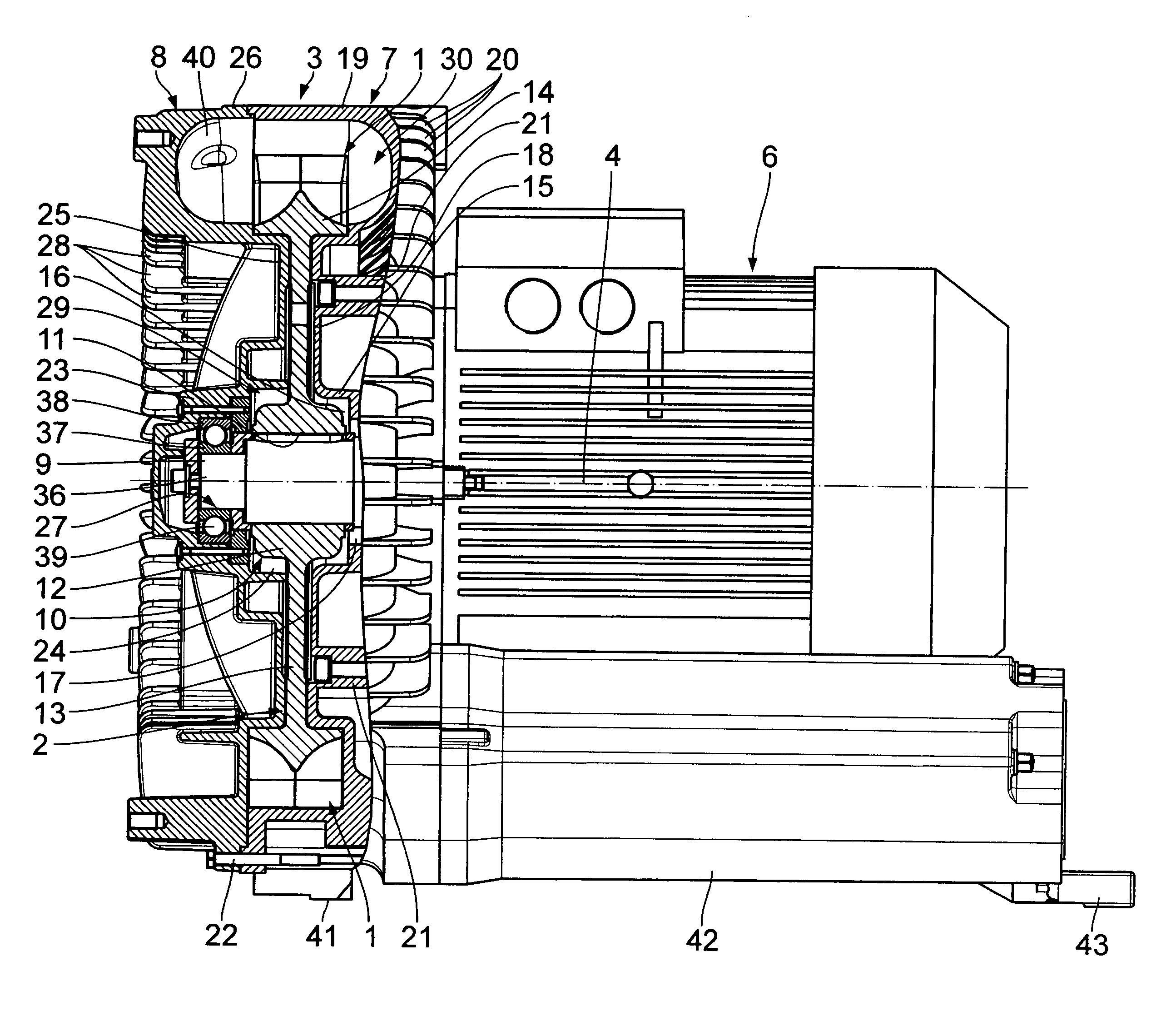
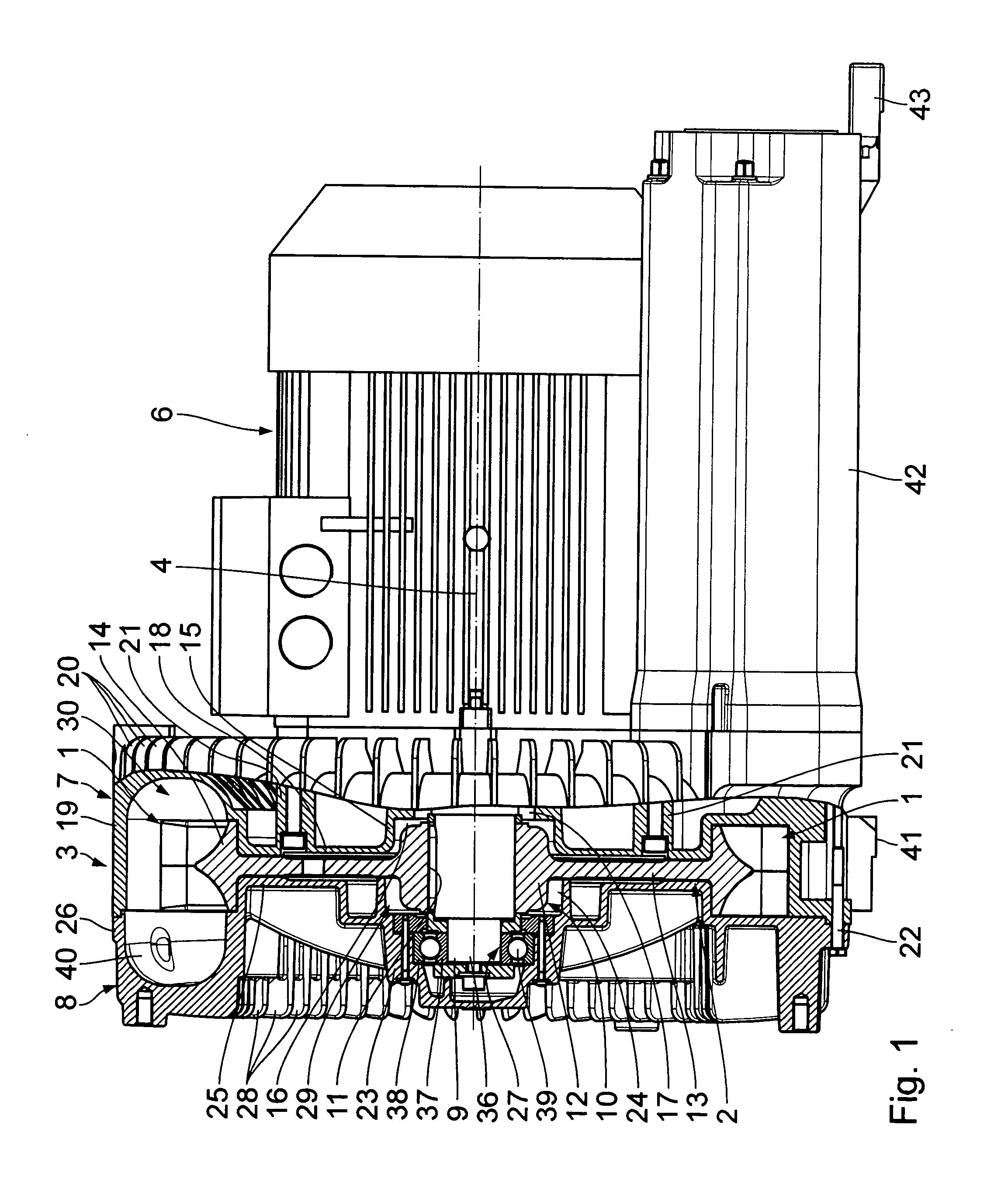
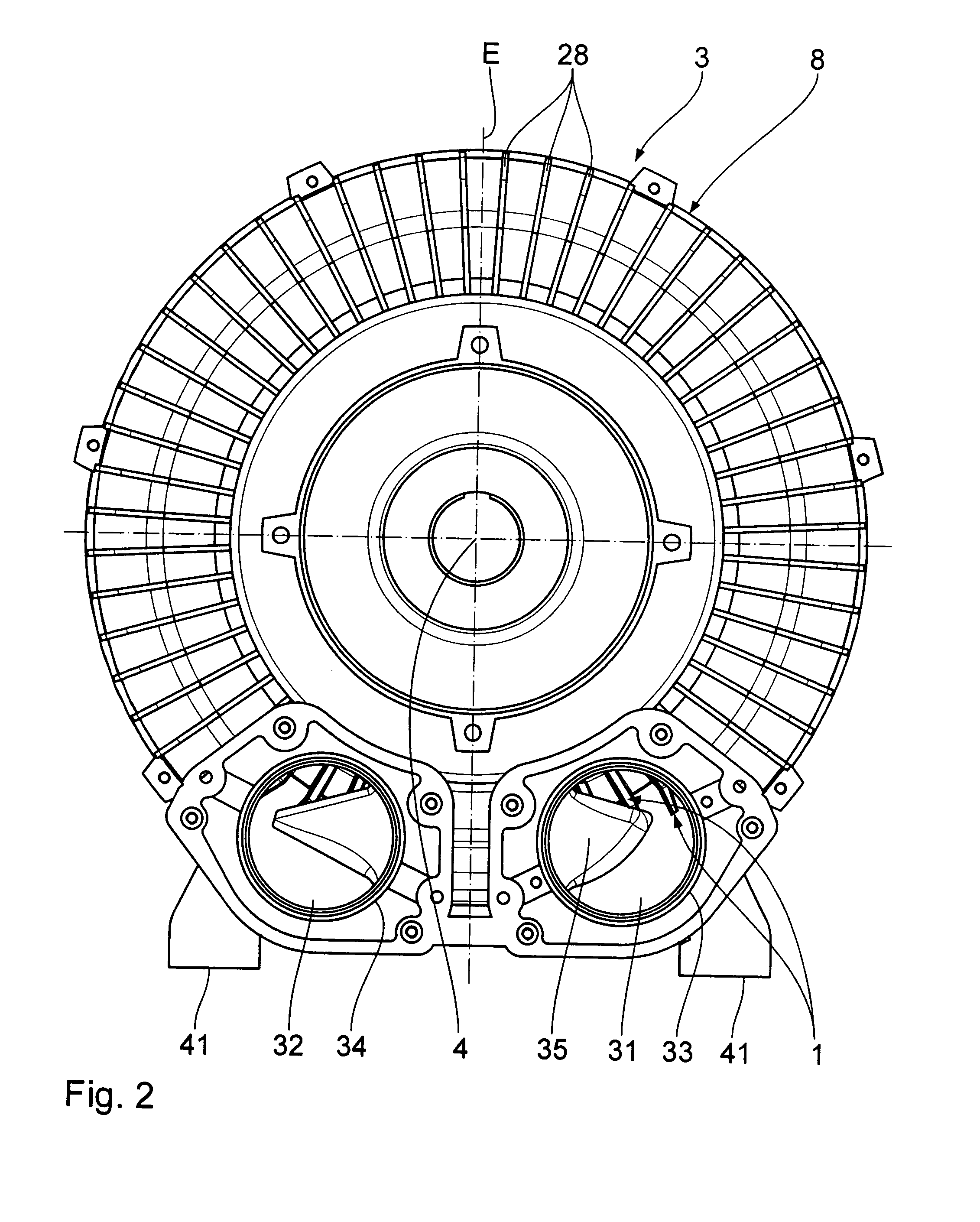
[0015]A side channel compressor shown in FIGS. 1 to 3 for compressing a gas comprises an impeller 2 which is equipped with impeller blades 1 and mounted for rotation about a horizontal central longitudinal axis 4 in a housing 3. A conventional drive 6 is used for rotary drive of the impeller 2 in the direction of the arrow 5. The gas is thus transported through the housing in the direction of the arrow 5 as well.

[0016]The housing 3 comprises a housing body 7 and a detachable housing cover 8 that are joined together according to FIGS. 1 and 2 so as to enclose the impeller 2 comprising the impeller blades 1, the impeller 2 being disposed for rotary drive on a drive shaft 9 for co-rotation therewith.

[0017]The impeller 2 is shaped like a disk. The impeller 2 comprises an inner impeller hub 10 with a central circular hub bore 11. The impeller hub 10 is formed by an inner hub foot 12 which radially outwardly delimits the hub bore 11, and by a radial circular hub washer 13 neighboring said...


PUM


Abstract

A side channel compressor for compressing a gas comprises a housing (3), a side channel (30), located in the housing (3) and having a cross-sectional area (A), for compressing a gas, a gas inlet opening (31) formed in the housing (3), the gas inlet opening (31) being in flow connection with the side channel (30) for introducing a gas, a gas outlet opening (32) formed in the housing (3) for discharging the gas to be compressed from the side channel (30), wherein the gas outlet opening (32) is in flow connection with the gas inlet opening (31) via the side channel (30), and an impeller (2) which is mounted for rotation in the housing (3) and comprises impeller blades (1) disposed in the side channel (30), wherein the cross-sectional area (A) of the side channel (30) decreases non-monotonically from the gas inlet opening (31) towards the gas outlet opening (32).

Description

BACKGROUND OF THE INVENTION[0001]1. Field of the Invention[0002]The invention concerns a side channel compressor for compressing a gas. The invention therefore concerns a work machine for compressing gases, such as air or technical gases.[0003]2. Background Art[0004]The operation of the side channel compressor results in a broadband sound spectrum. In conventional side channel compressors, tonal sound components occur at certain frequencies of the side channel compressor which are extremely annoying if they differ from the broadband sound spectrum by more than 7 dB.SUMMARY OF THE INVENTION[0005]It is the object of the invention to provide a side channel compressor which ensures a particularly silent operation.[0006]This object is achieved by a side channel compressor for compressing a gas, the side channel compressor comprising a housing; a side channel for compressing a gas, the side channel being located in the housing and having a cross-sectional area; a gas inlet opening formed ...

Claims


Application Information

Patent Timeline
Patent Type & Authority Patents(United States)
IPC IPC(8): F04D29/42
CPCF04D23/008F04D29/403
Inventor DITTMAR, RUDIKEMPF, MARIOGROHMANN, THOMAS
Owner GARDNER DENVER DEUTLAND
Why Eureka
Try Eureka