Drill rig and a method for controlling a fan therein

Inactive Publication Date: 2006-09-28
EPIROC ROCK DRILLS AB
View PDF12 Cites 0 Cited by
  • Summary
  • Abstract
  • Description
  • Claims
  • Application Information

AI Technical Summary

Benefits of technology

[0009] The present invention aims at obviating the above-mentioned disadvantages of previously known fan controls and presenting an improved solution. A primary object is to present a fan control, which provides a more efficient and more adapted cooling for the cooling elements of the drill rig. A second object is to present a fan control, which allows drill rigs to be used in colder climates without the components included in the drill rig running the risk of becoming overcooled. An additional object is to provide a drilling unit having closer-to-optimal temperature of the fluids that are in need of cooling. Still another object is to present a fan system being more silent in operation.
[0011] In a second aspect, the invention also relates to a drilling unit according to claim 7 for execution of the method. Preferred embodiments of the inventive drill rig are further seen in the dependent claims 8 to 16. The advantage of said method and device is that the speed of rotation / effect of the fan is adjustable, which entails that the air flow that passes through the cooling elements at each instant of time in a better way corresponds to the cooling demand that the same have at said instant of time. Thanks to the closer-to-optimal fluid temperatures with reduced temperature variations, the stress on the components of the systems decreases, which increases the service life of the same. By regulating the rotation speed of the fan, so that it does not operate with constantly high rotation speed (highest power), also the sound level in and around the drill rig is lowered. A lower rotation speed of the fan further entails a smaller power output from the engine and accordingly reduced fuel consumption.

Problems solved by technology

The problem with the above-mentioned way of controlling, or to be precise, not controlling the fans, is that the cooling elements that have lower cooling demand than what the fans provide run the risk of becoming overcooled, above all when the drill rig is used in cold climates.
An additional disadvantage of letting the fan operate at a constantly high rotation speed (highest power) is that the sound level from the fans and thereby also the sound level in the driver's cab is pronounced.

Method used


Image

  • Drill rig and a method for controlling a fan therein
  • Drill rig and a method for controlling a fan therein
  • Drill rig and a method for controlling a fan therein

Examples


Embodiment Construction

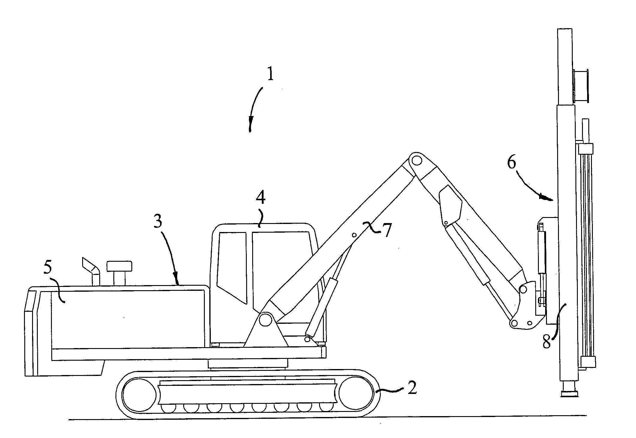
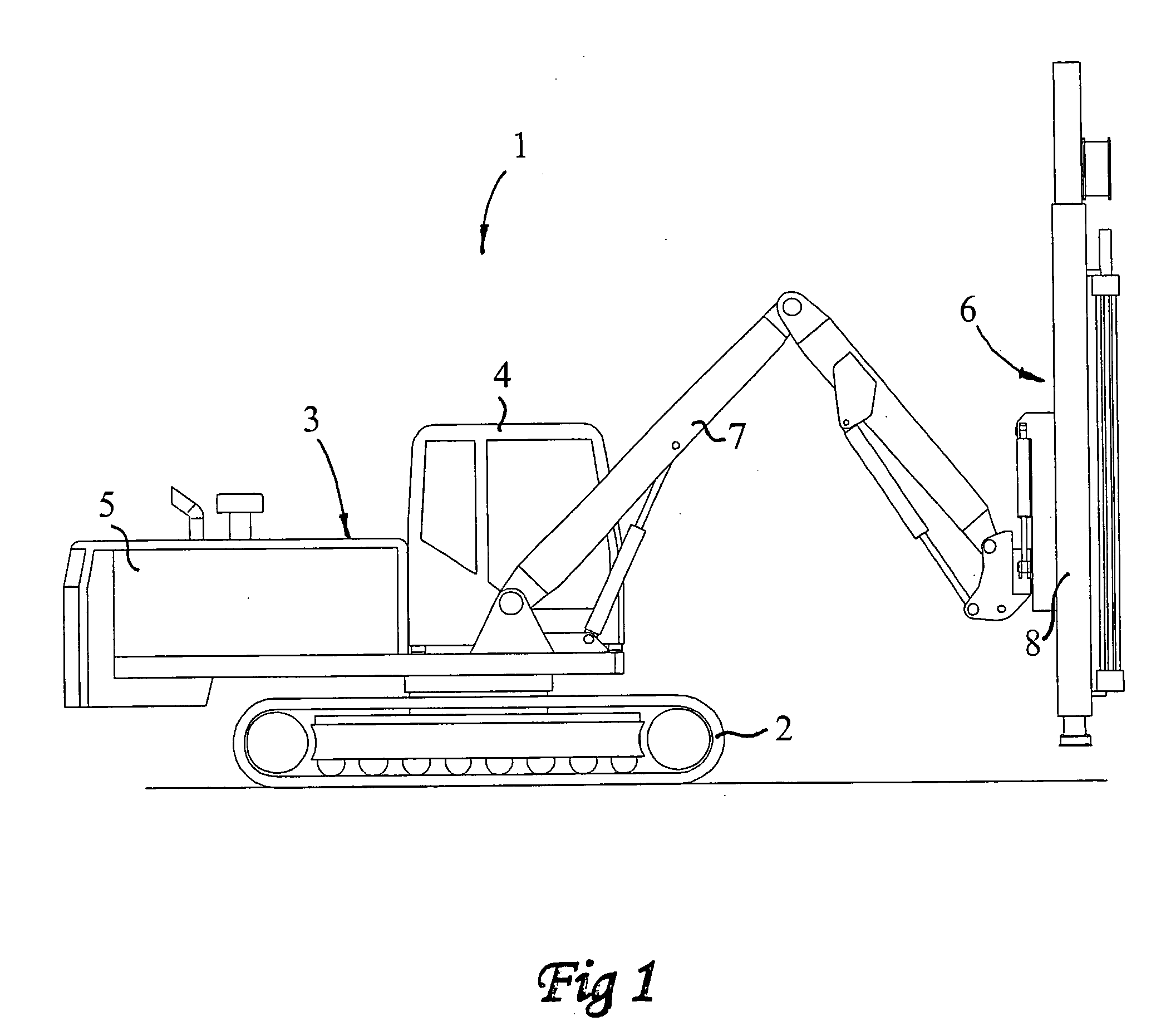
[0017] In FIG. 1, a drill rig according to the invention is shown, generally designated 1. The drill rig 1 comprises a carrier 3 carried by a pair of caterpillars 2, or the like, and comprising a driver's cab 4 and an engine house-forming chassis 5. The engine house 5 is in no way tight but comprises holes and openings so that good circulation of air therein is allowed. In the front part of the carrier 3, a feeder 6 is arranged, which is carried by one or more bars 7 and which comprises a drilling equipment 8, which is carried by the bars 7. The radius of working and accessibility of the drill rig 1 is determined by the bars 7 and the drilling equipment 8, which are of conventional type.

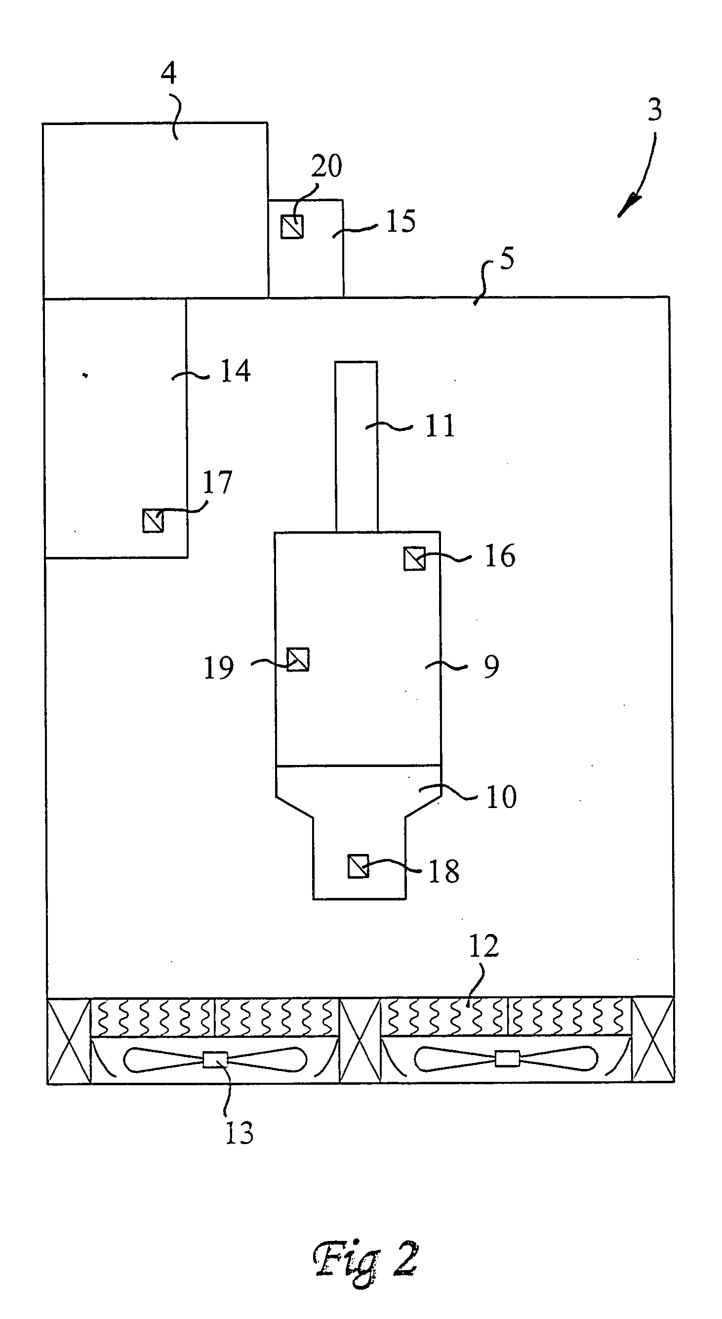
[0018] Now reference is made primarily to FIG. 2, in which a partially cut view from above of the carrier 3 of the drill rig 1 (a plurality of components are eliminated for the sake of clarity) is schematically shown. Centrally in the engine house 5, an engine 9 is arranged, preferably an internal c...


PUM


Abstract

In a method for controlling at least one fan (13) for the regulation of the cooling demand of at least two cooling elements (12) included in a drill rig (1), the cooling demand of each one of the cooling elements (12) being determined, that the determined cooling demands are weighted together and that the fan (13) is controlled based on the weighting together. At least one cooling element is equipped with a safety thermostat, which, if required, prevents undercooling by the fact that the fluid in question is not allowed to circulate in this cooling element. Also described is a drill rig for the execution of the above-mentioned method.

Description

TECHNICAL FIELD OF THE INVENTION [0001] This invention relates to a method for controlling at least one fan for the regulation of the cooling demand of at least two cooling elements comprised in a drill rig, the cooling demand of each one of the cooling elements being determined, that the determined cooling demands are weighted together and that the fan is controlled based on said weighting together. [0002] The invention also relates to a drill rig comprising an engine, at least two cooling elements and at least one fan, a control unit being arranged to control the fan based on a weighting together, executed in the control unit, of current cooling demands in the cooling elements. [0003] By drill rigs, in particular drill rigs for drilling in rock are intended and above all drill rigs for drilling in rock above ground. BACKGROUND OF THE INVENTION AND PRIOR ART [0004] The background of the present invention is the need of being able to provide cooling in a drill rig, or in a drilling ...

Claims


Application Information

Patent Timeline
IPC IPC(8): F01P7/14F01P7/02B60H1/00
CPCF01P5/02F01P7/04F01P2005/025F01P2023/00F01P2023/08F01P2025/13F01P2060/02F01P2060/04F01P2060/045
Inventor JACOBSSON, HENRIK
Owner EPIROC ROCK DRILLS AB
Why Eureka
Try Eureka