
Coupler

A coupling and upper coupling technology, applied in the field of mechanical parts, to achieve the effect of simple structure, large load torque and wide application range

Inactive Publication Date: 2017-05-24
CHENGDU 90 DEGREE IND PROD DESIGN CO LTD
View PDF0 Cites 0 Cited by
  • Summary
  • Abstract
  • Description
  • Claims
  • Application Information

AI Technical Summary

Problems solved by technology

[0004] The purpose of the present invention is to provide a shaft coupling for the above existing problems, which mainly solves the problem of large torque transmission during the use of the shaft coupling. The transmission of torque between them, the carrying torque is relatively large, the structure is simple, the use is convenient, and the application range is wide

Method used


Image

  • Coupler

Examples


Embodiment 1

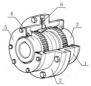
[0020] Such as figure 1 As described above, a shaft coupling is characterized in that it includes an upper joint body 2 and a lower joint body 1, and the upper joint body 2 and the lower joint body 1 are connected by a flange; the inner gear teeth of the upper joint body 2 are engaged with upper Connecting sleeve 4, the inner gear teeth of the lower connecting body 1 are engaged with the lower connecting sleeve 3; wherein the upper connecting sleeve 4 is sealed by a sealing ring on the end surface of the upper connecting body 2, and the lower connecting sleeve is sealed by a sealing ring on the end surface of the lower connecting body 1 3 sealed. Among them, a gear ring is arranged on the inner wall of the upper joint body 2, and a gear ring is arranged on the outer wall circumference of the upper joint sleeve 4, so that the gear ring of the upper joint sleeve 4 and the gear ring of the upper joint body 2 mesh with each other; As for the ring gear, a gear ring is arranged on ...


PUM


Abstract

The invention discloses a coupler, and belongs to the field of mechanical components. The coupler comprises an upper coupler body and a lower coupler body which are connected through a flange. Inner gear teeth of the upper coupler body are engaged with an upper coupler sleeve, and inner gear teeth of the lower coupler body are engaged with the lower coupler sleeve. The end face of the upper coupler body seals the upper coupler sleeve through a sealing ring, and the end face of the lower coupler body seals the lower coupler sleeve through a sealing ring. The problem about large torque transmission in the coupler using process is mainly solved, torque transmission between a shaft and the coupler can be achieved through gear transmission in the coupler, and the coupler is large in bearing torque, simple in structure, convenient and fast to use and wide in application range.

Description

technical field [0001] The invention relates to mechanical parts, especially a coupling. Background technique [0002] As a common component of power transmission, couplings have been widely used in various fields such as vehicles, mining machinery, pharmaceutical production, equipment manufacturing, etc., and have been greatly promoted for their superior power transmission performance. [0003] At present, the conventionally used couplings, during use, because the torque is transmitted between the shaft and the coupling, if the torque is too large, it will cause the shaft and the coupling to slip and fail, and it is easy to cause the coupling to fail. damage, and a safety accident occurs, so the existing coupling cannot meet the transmission of large torque. Contents of the invention [0004] The purpose of the present invention is to provide a shaft coupling for the above existing problems, which mainly solves the problem of large torque transmission during the use of t...

Claims


Application Information

Patent Timeline
IPC IPC(8): F16D1/033
CPCF16D3/185
Inventor 肖勇
Owner CHENGDU 90 DEGREE IND PROD DESIGN CO LTD
Learn More