
A led lighting device

A LED lighting and lighting technology, which is applied to lighting devices, lighting devices, lighting device components, etc., can solve the problems of untimely heat dissipation of LED lighting equipment, single function of LED lighting equipment, and heat dissipation, etc., to achieve rich data. Effects of transmission, increased range of use, and energy saving

Active Publication Date: 2019-07-16
福建明旺能源科技有限公司
View PDF2 Cites 0 Cited by
  • Summary
  • Abstract
  • Description
  • Claims
  • Application Information

AI Technical Summary

Problems solved by technology

[0003] The object of the present invention is to provide an LED lighting device to solve the above-mentioned background technology. Although when the LED lighting device emits light and generates heat energy, the heat energy can be directly transmitted to the heat dissipation ribs through the carrier plate, and the heat dissipation ribs and the housing will transfer the heat energy to the cooling ribs. The heat energy is dissipated, thereby stabilizing the working temperature of the LED lighting device and prolonging the service life, but the heat generated by the LED lighting device cannot be completely dissipated only by the heat dissipation of the cooling ribs, especially when the LED lighting device works for a long time, the LED lighting The device will generate a lot of heat with the prolongation of the use time, and the heat dissipation ribs will store part of the heat while conducting heat for a long time, which will cause the heat dissipation of the LED lighting equipment to be delayed, and the function of this LED lighting equipment is single , cannot meet the problems of today's high-tech life

Method used


Image

  • A led lighting device
  • A led lighting device
  • A led lighting device

Examples


Embodiment Construction

[0015] The following will clearly and completely describe the technical solutions in the embodiments of the present invention with reference to the accompanying drawings in the embodiments of the present invention. Obviously, the described embodiments are only some, not all, embodiments of the present invention. Based on the embodiments of the present invention, all other embodiments obtained by persons of ordinary skill in the art without making creative efforts belong to the protection scope of the present invention.

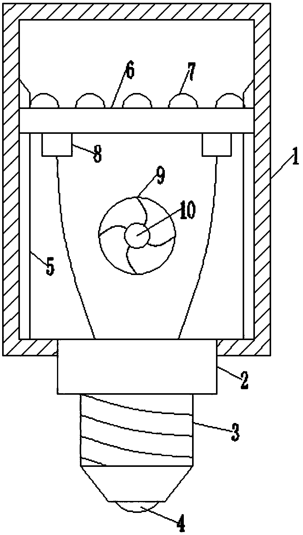
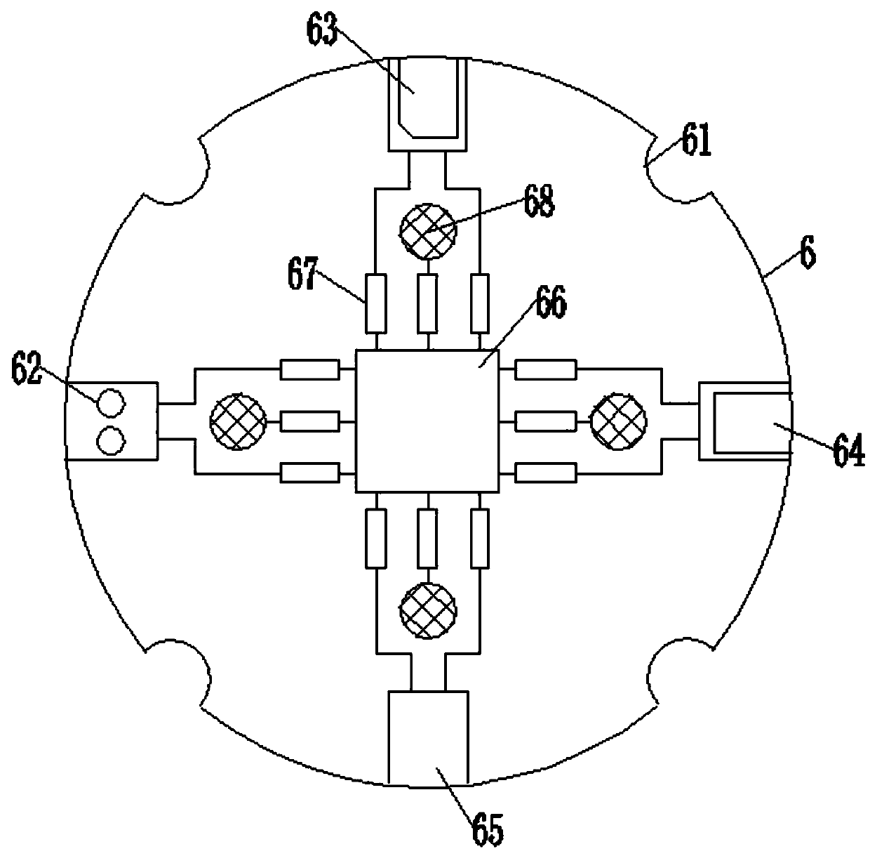
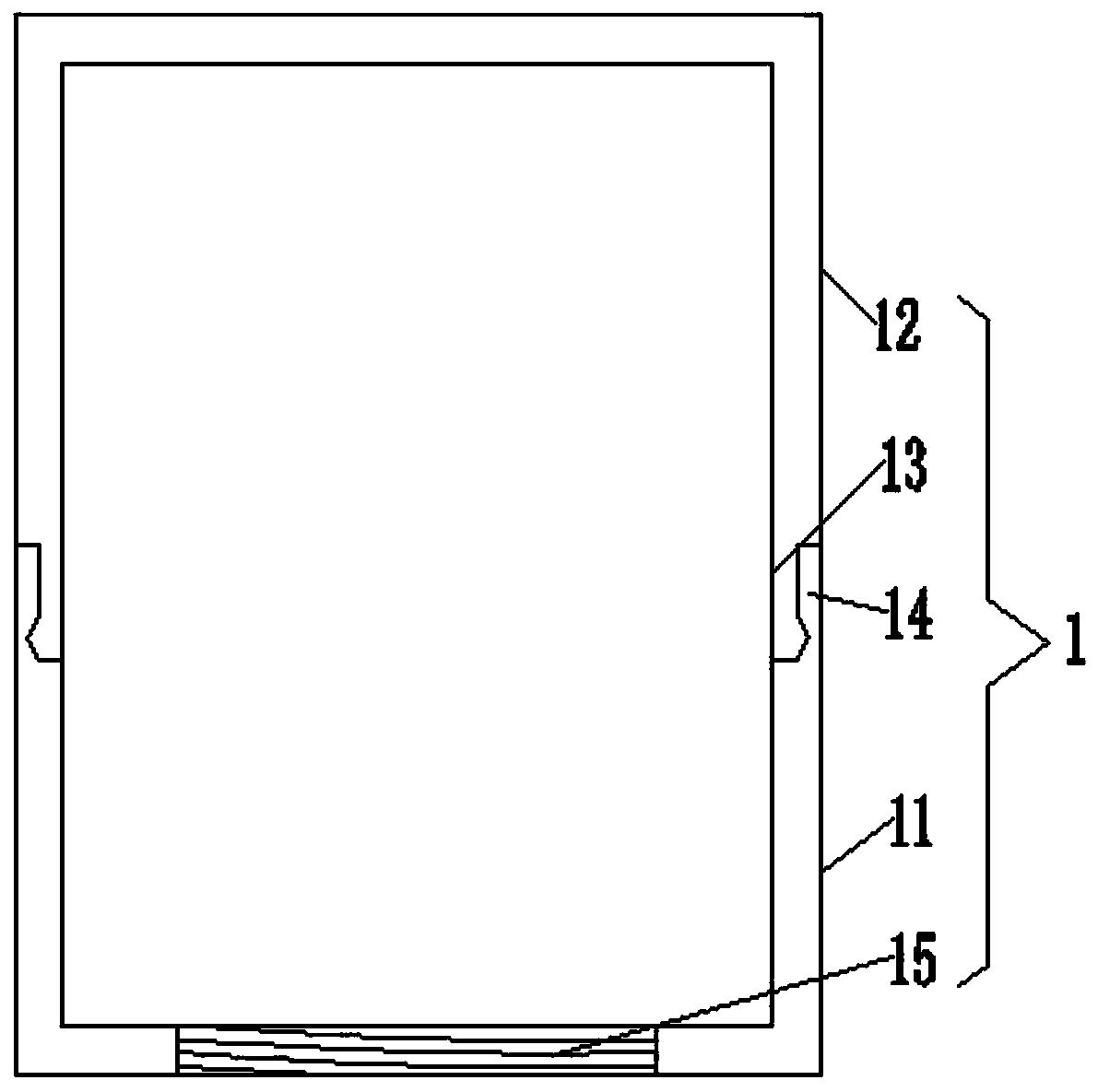
[0016] see Figure 1-5 , the present invention provides a technical solution: an LED lighting device, including a light cover 1, the bottom of the light cover 1 is provided with a connecting column 2, and the bottom of the connecting column 2 is provided with a lamp holder 3, and the lamp holder The bottom of 3 is provided with contacts 4, and the left and right sides of the inner cavity of the light cover 1 are provided with support plates 5, the structures o...


PUM


Abstract

The invention discloses a three-dimensional LED circuit board and an LED illumination device which are used in the technical field of LED illumination. The LED illumination device comprises a lamplight housing. A connecting pillar is arranged at the bottom of the lamplight housing. A lamp holder is arranged at the bottom of the connecting pillar. A contact is arranged at the bottom of the lamp holder. The left side and the right side of an inner chamber of the lamplight housing are each provided with a support plate. The two support plates are the same in structure. According to the three-dimensional LED circuit board and the LED illumination device, through cooperation between a heat dissipation hole and a heat dissipation fan, heat generated in the LED illumination device can be conducted out in time; meanwhile, when the LED illumination device is used for a long time, a good heat dissipation effect can still be guaranteed, and the situation that the heat is not dissipated in time due to heat storage is avoided; and a central processor is electrically connected with the heat dissipation fan, the heat dissipation fan can be controlled to work and stop through the central processor, thus heat dissipation of the heat dissipation fan can be controlled, it is guaranteed that the heat dissipation fan can conduct heat dissipation reasonably, and energy is saved.

Description

technical field [0001] The invention relates to the technical field of LED lighting, in particular to an LED lighting device. Background technique [0002] Light-emitting diodes (LEDs) have been widely used in decorative lights and display screens due to their long service life, energy saving, and environmental pollution-free environmental protection. Problems such as good quality and other problems make LEDs not suitable for lighting applications in the early stage. With the advancement of technology, the unit output power and luminous brightness have been gradually improved, and the problem of insufficient brightness has been solved. However, the higher the power consumption of LEDs, the accompanying heat energy is also The more, the excessive heat energy will make the temperature of the lamp continue to rise, which will have a considerable negative impact on the life and luminous efficiency of the LED (blank space). The improved structure of the lighting device, the LED ...

Claims


Application Information

Patent Timeline
Patent Type & Authority Patents(China)
IPC IPC(8): F21K9/232F21V19/00F21V29/83F21V29/67F21V17/16F21V33/00F21Y115/10
CPCF21V17/164F21V19/0015F21V29/677F21V29/83F21V33/0056
Inventor 宋竞雄周金柱
Owner 福建明旺能源科技有限公司
Learn More