Device for adjusting damping ratio of sensor

An adjustment device and damping adjustment technology, applied in the field of sensors, can solve the problems of narrow frequency bandwidth, large damping ratio, obvious resonance frequency points of the sensor, etc., to achieve the effect of ensuring accuracy

Pending Publication Date: 2017-05-24
匙庆磊
View PDF7 Cites 2 Cited by
  • Summary
  • Abstract
  • Description
  • Claims
  • Application Information

AI Technical Summary

Problems solved by technology

[0004] First, connect a resistor in parallel with the sensor to increase the damping ratio to form a velocity pendulum accelerometer. This method is a passive servo feedback method. Its shortcoming is that there is a limit to increasing the damping by connecting resistors in parallel. After the ratio is increased to 3-5, limited by the mechanical parameters of the sensor, it is difficult to increase the damping, and the width of the frequency band used by the sensor is narrow;
[0005] Second, design two sets of coils on the moving coil transducer sensitive element, one set is the signal coil, and the other set is the feedback coil. The signal of the signal coil is added to the feedback coil after passing through the feedback circuit. This method can obtain larger The damping ratio, the disadvantage is that due to the influence of coil self-inductance and mutual inductance, the sensor has an obvious resonance frequency point

Method used


Image

  • Device for adjusting damping ratio of sensor
  • Device for adjusting damping ratio of sensor
  • Device for adjusting damping ratio of sensor

Examples


Embodiment Construction

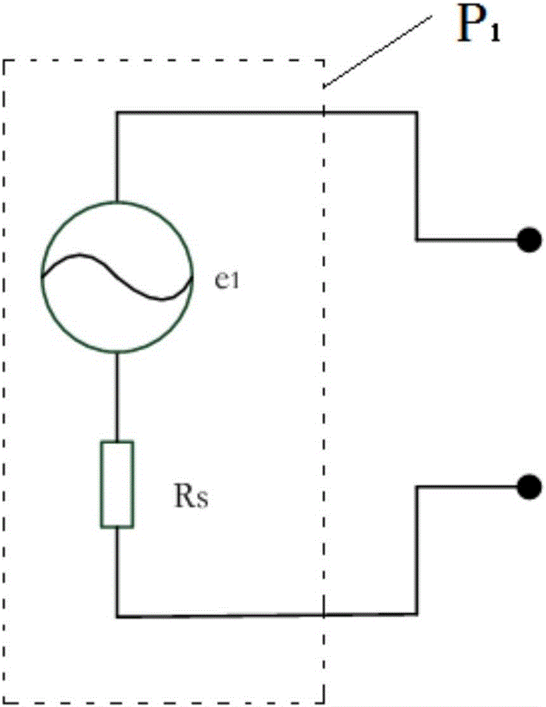
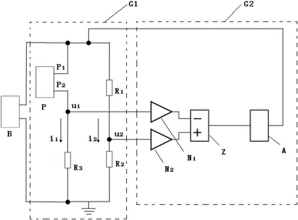
[0023] Please also see figure 1 and figure 2 , figure 1 is the equivalent circuit diagram of the sensor of the present invention; figure 2 It is a schematic diagram of the circuit structure for adjusting the damping ratio of the sensor in the present invention. The sensor damping ratio adjustment device includes sensor B, damping adjustment circuit G 1 and voltage processing circuit G 2 . The output terminal of the sensor B is connected with the damping adjustment circuit G 1 The input terminal is connected; the damping adjustment circuit G 1 output of the voltage processing circuit G with the 2 The input terminal of the voltage processing circuit G2 is connected to the output terminal of the sensor B, and the damping adjustment circuit G 1 The pressure difference signal is fed back to the sensor B, and then the sensor B outputs a damping ratio signal.

[0024] The damping adjustment circuit G 1 including the first resistor R 1 , the second resistance R 2 , the t...


PUM


Abstract

The invention relates to a device for adjusting the damping ratio of a sensor, and the device comprises a sensor, a damping adjustment circuit and a voltage processing circuit. The output end of the sensor is connected with the input end of the damping adjustment circuit. The output end of the damping adjustment circuit is connected with the input end of the voltage processing circuit. The output end of the voltage processing circuit is connected with the output end of the sensor, and the voltage processing circuit enables a voltage difference signal of the damping adjustment circuit to be fed back to the sensor, and the sensor outputs a damping ratio signal. Compared with the prior art, the device can facilitate the change of the damping ratio of the sensor through the designing of the damping adjustment circuit and the voltage processing circuit and the changing of the parameters of the damping adjustment circuit and the voltage processing circuit. Furthermore, the device can obtain a bigger damping ratio without changing the internal mechanical structure of the sensor, does not has a resonance ratio point, and guarantees the detection accuracy of the sensor.

Description

technical field [0001] The invention relates to the field of sensors, in particular to a sensor damping ratio adjustment device. Background technique [0002] The dynamic transduced inertial sensor is a common vibration measurement sensor. The moving coil transducer inertial sensor uses the principle of electromagnetic induction to place the coil in a magnetic field. After the sensor is vibrated by the outside world, the coil also moves accordingly. The coil moves to cut the magnetic force line to generate an induced electromotive force, thereby measuring the external motion. The vibration physical quantity measured by the moving coil transducer inertial sensor can be velocity or acceleration. [0003] The difference in measured physical quantity is realized by adjusting the damping ratio of the moving coil transducer inertial sensor. When the sensor is in a small damping state, the physical quantity measured by the sensor is velocity; when the sensor is in a large damping ...

Claims


Application Information

Patent Timeline
Patent Type & Authority Applications(China)
IPC IPC(8): G01D5/16
CPCG01D5/16
Inventor 匙庆磊
Owner 匙庆磊
Why Eureka
Try Eureka