Finite element model-based aircraft motion surface deflection method

A moving surface, finite element technology, applied in instruments, geometric CAD, calculations, etc., can solve problems such as the inability to realize the loaded state, and achieve the effect of rapid deflection of the model, accurate analysis results, and realization of parameterization and automation.

Active Publication Date: 2017-05-24
XIAN AIRCRAFT DESIGN INST OF AVIATION IND OF CHINA
View PDF3 Cites 3 Cited by
  • Summary
  • Abstract
  • Description
  • Claims
  • Application Information

AI Technical Summary

Problems solved by technology

This method is feasible for the independent solution of the rudder surface, but when it is necessary to connect the active surface and the box segment to simulate

Method used


Image

  • Finite element model-based aircraft motion surface deflection method
  • Finite element model-based aircraft motion surface deflection method
  • Finite element model-based aircraft motion surface deflection method

Examples


Embodiment Construction

[0024] Take a certain type of aircraft elevator as an example to introduce the specific operation process of the deflection of the movable surface of the aircraft:

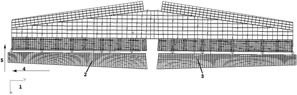
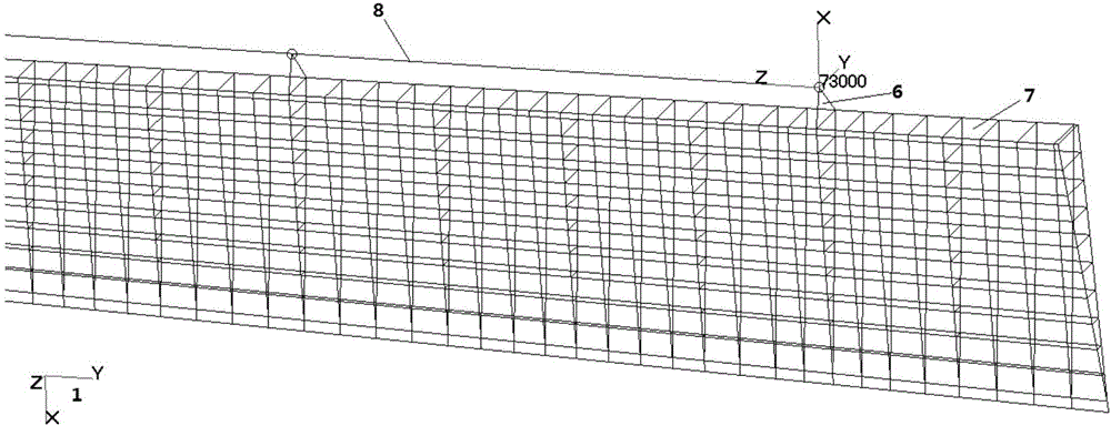
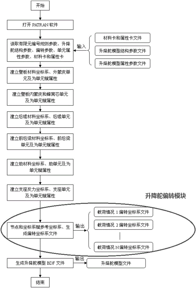
[0025] Step 1. In the basic coordinate system, that is, the overall coordinate system of the aircraft, a finite element model of the neutral position of the elevator is established, such as figure 1 The basic coordinate system shown in 1, the finite element model of the neutral position of the left elevator 2, the finite element model of the neutral position of the right elevator 3, the neutral position of the elevator is the position when the deflection angle of the elevator is 0 degrees. In this step, the conventional finite element modeling method is programmed to avoid the tedious work of manually generating a large number of nodes and elements. Such as image 3 Shown is the flow chart of the elevator parametric modeling program, and the elevator deflection module is the part that will be highlighted next.

...


PUM


Abstract

The invention belongs to the field of aircraft strength calculation and relates to a finite element model-based aircraft motion surface deflection method. The method comprises the following steps of 1, building a motion surface finite element model of a neutral position in a basic coordinate system; 2, establishing a reference deflection coordinate system in the motion surface finite element model of the neutral position, wherein an original point of the coordinate system is a lug hole center of a suspension support, an X axis is perpendicular to a front beam plane of a motion surface, a front edge direction is positive, a Z axis is a rotary axis of the motion surface, a wing tip direction is positive, and a Y axis is determined by a right-hand rule; 3, defining coordinates of all nodes of the motion surface finite element model of the neutral position in the reference deflection coordinate system; and 4, generating a deflection coordinate system by enabling the reference deflection coordinate system to deflect around the Z axis of the reference deflection coordinate system for a required angle, thereby realizing the deflection of the motion surface of an aircraft. The finite element model-based aircraft motion surface deflection method is provided.

Description

technical field [0001] The invention belongs to the field of aircraft strength calculation, and relates to an aircraft active surface deflection method based on a finite element model. Background technique [0002] In aircraft strength analysis, the traditional solution to the problem of multi-deflection loading on the movable surface is to only establish the finite element model of the neutral position of the movable surface, and to use the deflection method of the actuator relative to the movable surface for loads with deflection angles To simulate the change of the control arm due to the deflection of the active surface. This method is feasible for the sole solution of the rudder surface, but when it is necessary to connect the active surface and the box segment to simulate a more realistic support stiffness, this method cannot realize the loading state of the active surface with different deflection angles under multiple load cases. Contents of the invention [0003] ...

Claims


Application Information

Patent Timeline
IPC IPC(8): G06F17/50
CPCG06F30/15G06F30/23
Inventor 李苗陈军李军贵郑洁
Owner XIAN AIRCRAFT DESIGN INST OF AVIATION IND OF CHINA
Why Eureka
Try Eureka