Multi-antenna radio frequency circuit and radio-frequency signal processing method

A radio frequency signal and radio frequency circuit technology, applied in the field of signal processing, can solve the problems of insufficient bandwidth coverage of a single antenna, failure of multi-antenna multi-transceiver circuits, and the inability of a single antenna to further effectively widen the antenna bandwidth.

Inactive Publication Date: 2017-05-24
XIAN ZHONGXING NEW SOFTWARE
View PDF7 Cites 8 Cited by
  • Summary
  • Abstract
  • Description
  • Claims
  • Application Information

AI Technical Summary

Problems solved by technology

At present, wireless terminals are limited by requirements such as cost and size, and a single antenna cannot further effectively widen the antenna bandwidth
Therefore, multi-antenna technology is gradually introduced in the design of wireless terminals to solve the problem of insufficient bandwidt

Method used


Image

  • Multi-antenna radio frequency circuit and radio-frequency signal processing method
  • Multi-antenna radio frequency circuit and radio-frequency signal processing method
  • Multi-antenna radio frequency circuit and radio-frequency signal processing method

Examples


Embodiment 1

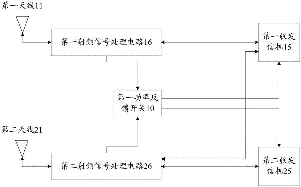
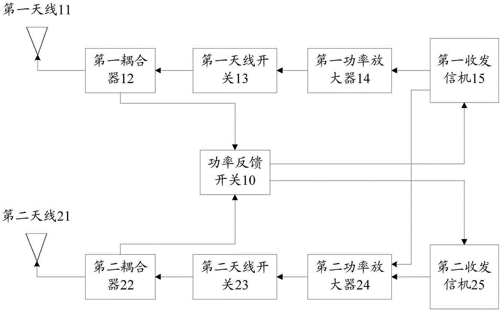
[0152] This example takes dual antennas as an example. The workflow for the high-frequency band is as follows: the high-frequency signal is output from the main transceiver and enters the high-frequency power amplifier for amplification; the amplified high-frequency signal is connected to the high-frequency antenna switch through the high-frequency antenna switch. High-frequency coupler, high-frequency antenna switch realizes the connection between the hardware channel of different high-frequency bands and the high-frequency coupler; the high-frequency signal transmitted to the high-frequency coupler is divided into two channels, and the main signal is output through the high-frequency coupler To the high-frequency antenna, the high-frequency coupling signal is output from the coupling port of the high-frequency coupler, and transmitted to the main transceiver through the power feedback switch; the detector inside the main transceiver detects the high-frequency feedback signal, ...

Embodiment 2

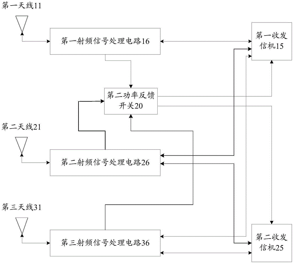
[0155] This example takes three antennas as an example. The workflow for the high-frequency band is as follows: the high-frequency signal is output from the main transceiver and enters the high-frequency power amplifier for amplification; the amplified high-frequency signal is connected to the high-frequency antenna switch through the high-frequency antenna switch. High-frequency coupler, high-frequency antenna switch realizes the connection between the hardware channel of different high-frequency bands and the high-frequency coupler; the high-frequency signal transmitted to the high-frequency coupler is divided into two channels, and the main signal is output through the high-frequency coupler To the high-frequency antenna, the high-frequency coupling signal is output from the coupling port of the high-frequency coupler, and transmitted to the main transceiver through the power feedback switch; the detector inside the main transceiver detects the high-frequency feedback signal,...


PUM


Abstract

The invention discloses a multi-antenna radio frequency circuit and a radio-frequency signal processing method. The radio frequency circuit at least comprises a first antenna, a first radio-frequency signal processing circuit, a second antenna, a second radio-frequency signal processing circuit, a first transceiver, and a second transceiver. The first antenna and the first radio-frequency signal processing circuit are connected; the second antenna and the second radio-frequency signal processing circuit are connected; the first transceiver connected with the first radio-frequency signal processing circuit and the second radio-frequency signal processing circuit is used for outputting a first frequency band signal in the first kind of radio frequency signals to the first radio-frequency signal processing circuit and outputting a second frequency band signal in the first kind of radio frequency signals to the second radio-frequency signal processing circuit; and the second transceiver connected with the second radio-frequency signal processing circuit is used for outputting a second frequency band signal in the second kind of radio frequency signals to the second radio-frequency signal processing circuit.

Description

technical field [0001] The invention relates to signal processing technology, in particular to a multi-antenna radio frequency circuit and a radio frequency signal processing method. Background technique [0002] With the development of Long Term Evolution (LTE, Long Term Evolution) technology, wireless terminals are required to support a wider communication bandwidth, which poses a greater challenge to antenna design. Currently, wireless terminals are limited by requirements such as cost and size, and a single antenna cannot further effectively widen the antenna bandwidth. For this reason, multi-antenna technology is gradually introduced in wireless terminal design to solve the problem of insufficient bandwidth coverage of a single antenna. [0003] The emergence of multiple antennas puts forward new requirements for the radio frequency circuit of the wireless terminal. The current multiple antennas have only one transceiver, and the circuit of multiple antennas and multip...

Claims


Application Information

Patent Timeline
IPC IPC(8): H04B1/40
CPCH04B1/006H04B1/0064H04W52/243H04B1/38H04B7/0608
Inventor 谢卫博
Owner XIAN ZHONGXING NEW SOFTWARE
Why Eureka
Try Eureka