
Electric appliance cabinet and dustproof control method

A kind of electrical cabinet, dustproof technology, applied in the direction of electrical components, electrical equipment structural parts, cooling/ventilation/heating transformation, etc., can solve the problems of loss, short circuit of electrical components of electrical cabinets, circuit damage

Inactive Publication Date: 2017-05-24
STATE GRID SHANDONG ELECTRIC POWER CO WEISHAN POWER SUPPLY CO +1
View PDF6 Cites 4 Cited by
  • Summary
  • Abstract
  • Description
  • Claims
  • Application Information

AI Technical Summary

Problems solved by technology

[0002] At present, after the traditional electrical cabinet has been running for a long time, a large amount of dust will accumulate on the cabinet and inside the cabinet due to static electricity. A large amount of dust will easily short-circuit the electrical components inside the electrical cabinet, causing damage to the circuit and bringing unnecessary Loss

Method used


Image

  • Electric appliance cabinet and dustproof control method
  • Electric appliance cabinet and dustproof control method
  • Electric appliance cabinet and dustproof control method

Examples


no. 1 example

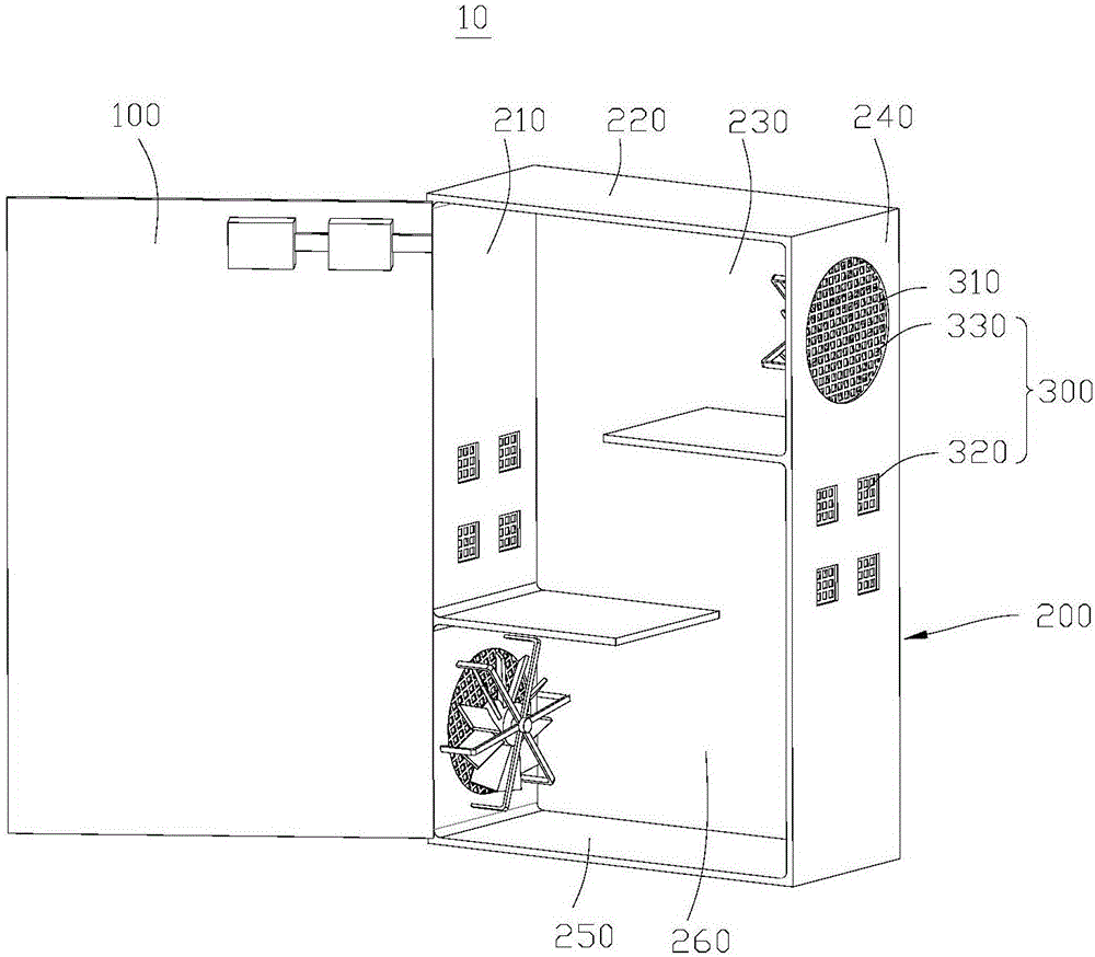
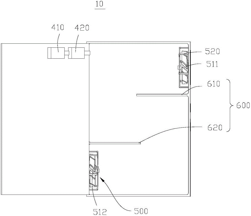
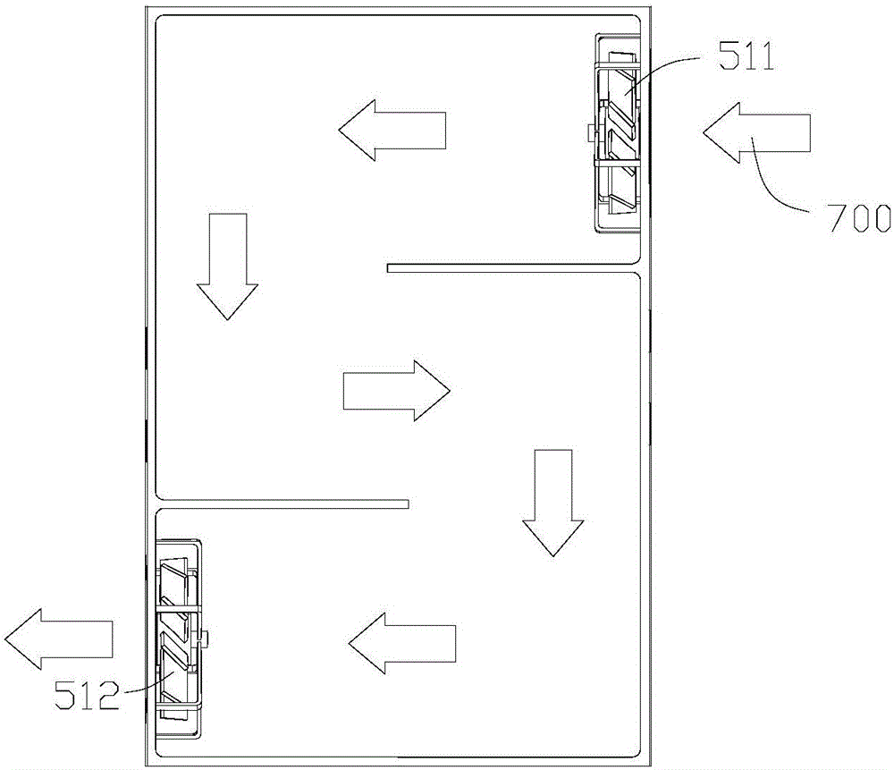
[0034] see figure 1 , figure 1 The schematic diagram of the structure of the electrical cabinet 10 provided by the first embodiment in the first viewing angle. The electrical cabinet 10 includes a cabinet door 100 and a cabinet body 200 . The cabinet 200 includes a first side panel 210, a second side panel 240, a top panel 220, a bottom panel 250 and a third side panel 230, and the first side panel 210 and the second side panel 240 are oppositely arranged on both sides of the third side panel 230 , the top plate 220 and the bottom plate 250 are relatively arranged on both sides of the third side plate 230, and the top plate 220, the first side plate 210, the second side plate 240 and the bottom plate 250 enclose an accommodating space 260, the accommodating space 260 Used to install electrical components (not shown). Wherein, the cabinet door 100 is connected to the cabinet body 200 to open or close the accommodating space 260 .

[0035] In this embodiment, vent holes 300 ...

no. 2 example

[0055] see Figure 7 , Figure 7It is a flow chart of the dustproof control method for the electrical cabinet 10 provided in the second embodiment. The second embodiment of the present invention provides a dust-proof control method for performing dust-proof control on the electrical cabinet 10 provided in the first embodiment. The dust control method is as follows:

[0056] Step S101, turn on the fan 500, and the fan 500 starts in the first working state by default.

[0057] Step S102, judging that the electrical component is in the first operating state or the second operating state. Wherein, the first operating state is a state when the electrical components are operating with a low load, and the second operating state is a state where the electrical components are operating with a high load.

[0058] If the electrical component is in the first operating state, go to step S103.

[0059] Step S103 , judging whether the fan 500 has worked in the first working state for a ...


PUM


Abstract

The invention provides an electric appliance cabinet and a dustproof control method, and relates to an electric appliance cabinet field. The electric appliance comprises a cabinet door and a cabinet body. The cabinet door is connected with the cabinet body. The cabinet body comprises a first side plate, a second side plate, a top plate, a bottom plate, and a third side plate. The first side plate, the second side plate, the top plate, and the bottom plate are used to form a frame in an encircled manner, and are connected with the side surface of the third side plate to form accommodation space. The cabinet door can be used to open the accommodation space selectively. The side plate of the cabinet body is provided with a through hole, which is provided with a dustproof filter screen to prevent dust in air from entering the accommodation space, and is provided with a fan. The fan has different working states, and the working states of the fan can be switched to achieve dustproof effect and automatic dedusting effect.

Description

technical field [0001] The invention relates to the field of electrical cabinets, in particular to an electrical cabinet and a dust-proof control method. Background technique [0002] At present, after the traditional electrical cabinet has been running for a long time, a large amount of dust will accumulate on the cabinet and inside the cabinet due to static electricity. A large amount of dust will easily short-circuit the electrical components inside the electrical cabinet, causing damage to the circuit and bringing unnecessary Loss. Contents of the invention [0003] The purpose of the present invention is to provide an electrical cabinet, which can prevent dust and remove dust automatically. [0004] Another object of the present invention is to provide a dust-proof control method, which can perform dust-proof and automatic dust-removal for electrical cabinets. [0005] The invention provides a technical solution: [0006] An electrical cabinet includes a cabinet bo...

Claims


Application Information

Patent Timeline
Patent Type & Authority Applications(China)
IPC IPC(8): H05K7/20
CPCH05K7/20136H05K7/20209
Inventor 曹长华王涛渠涛王猛刘清静
Owner STATE GRID SHANDONG ELECTRIC POWER CO WEISHAN POWER SUPPLY CO
Learn More