Lower limb joint recovery bed mattress

A technology of joints and mattresses, applied in the field of mattresses, which can solve problems such as patients using alone and rehabilitation medical equipment being inaccessible

Inactive Publication Date: 2017-05-31
四川送到家科技有限公司
View PDF0 Cites 2 Cited by
  • Summary
  • Abstract
  • Description
  • Claims
  • Application Information

AI Technical Summary

Problems solved by technology

[0004] The technical problem to be solved by the present invention is that the rehabilitation medical device cannot be used by the patient alone, and the purpose is to provide a lower limb joint rehabilitation mattress, which solves the above problems

Method used


Image

  • Lower limb joint recovery bed mattress
  • Lower limb joint recovery bed mattress

Examples


Embodiment 1

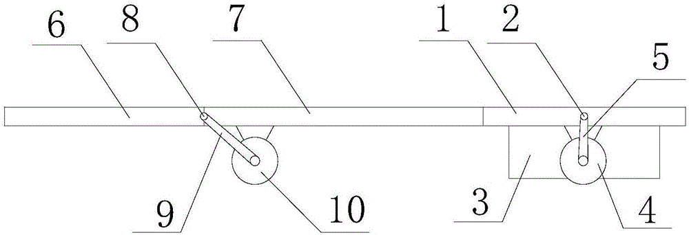
[0028] Such as figure 1 , figure 2 As shown, a lower limb joint rehabilitation mattress according to the present invention includes an overturning pad 1, a first rotating shaft 2, a rehabilitation instrument 3, a first motor 4 and a first transmission device 5; the first rotating shaft 2 is horizontally and fixedly installed on the overturning pad 1; both ends of the first rotating shaft 2 are installed on the bed frame; the rehabilitation instrument 3 is fixedly installed on the flipping pad 1; the first transmission device 5 is connected to the output end of the first motor 4 and transmits power to the first The rotating shaft 2 makes the first rotating shaft 2 rotate around its axis; when the first rotating shaft 2 rotates, it drives the turning pad 1 to rotate around the axis of the first rotating shaft 2 .

[0029] When this embodiment is implemented, the first motor 4 drives the first rotating shaft 2 to rotate around its axis through the first transmission device 5; w...

Embodiment 2

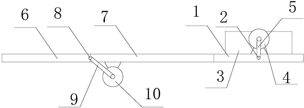
[0031] Such as figure 1 , figure 2 As shown, on the basis of Embodiment 1, this embodiment also includes a backrest cushion 6, a second rotating shaft 8, a second transmission device 9 and a second motor 10; the second rotating shaft 8 is horizontally and fixedly installed on the backrest cushion 6; Both ends of the second rotating shaft 8 are installed on the bed frame; the second transmission device 9 is connected to the output end of the second motor 10 and transmits power to the second rotating shaft 8 so that the second rotating shaft 8 rotates around its axis; When the second rotating shaft 8 rotates, the back cushion 6 is driven to rotate around the axis of the second rotating shaft 8 .

[0032] During the implementation of this embodiment, if the patient needs to sit up and use the rehabilitation instrument 3, the second motor 10 drives the second rotating shaft 8 to rotate around its axis through the second transmission device 9, and when the second rotating shaft 8...

Embodiment 3

[0034] Such as figure 1 , figure 2 As shown, on the basis of Embodiment 2, this embodiment also includes a fixed pad 7; the fixed pad 7 is horizontally installed on the bed frame, and the backrest pad 6, the fixed pad 7 and the turning pad 1 are arranged in sequence along the horizontal direction.

[0035] When the present embodiment is implemented, when the whole device is in the standby state, the backrest pad 6, the fixed pad 7 and the turning pad 1 are horizontally arranged sequentially, so that the patient can lie comfortably on the mattress.


PUM


Abstract

The invention discloses a lower limb joint recovery bed mattress. The lower limb joint recovery bed mattress comprises an overturning pad, a first rotation shaft, a recovery instrument, a first motor and a first transmission device. The first rotation shaft is horizontally and fixedly installed on the overturning pad. Two ends of the first rotation shaft are installed on a bed frame. The recovery instrument is fixedly installed on the overturning pad. The first transmission device is connected with the output end of the first motor and transmits the power to the first rotation shaft so that the first rotation shaft is rotated around the axis. The first rotation shaft drives the overturning pad to be rotated around the axis of the first rotation shaft during the rotation process. The lower limb joint recovery bed mattress can be freely switched by a patient from the working state to the standby state, so the patient can conveniently use the recovery instrument without nursing.

Description

technical field [0001] The invention relates to a mattress, in particular to a rehabilitation mattress for lower limb joints. Background technique [0002] Traveling, taking a bath, and getting out of bed are easy things for healthy people, but for patients after limb surgery, it is an adventure, even a task that is impossible to complete by themselves. And those rehabilitation medical devices that can help patients perform physical therapy, functional exercise, and restore self-care and labor ability are being welcomed by more and more patients. According to the concept of the World Health Organization, medicine is a natural science for maintaining health, which is composed of preventive medicine, health care medicine, therapeutic medicine and rehabilitation medicine. It can be seen that rehabilitation medicine is an important part of medical services. Therefore, in the process of treatment and rehabilitation, patients will inevitably come into contact with rehabilitation ...

Claims


Application Information

Patent Timeline
Patent Type & Authority Applications(China)
IPC IPC(8): A61G7/05
CPCA61G7/05A61G2203/10
Inventor 洪喜峰
Owner 四川送到家科技有限公司
Why Eureka
Try Eureka