UV LED line light source curing machine

A technology of curing machine and line light source, applied in the direction of pretreatment surface, coating, device for coating liquid on the surface, etc., can solve the problems of inconspicuousness, cannot increase too much, and the effect is not satisfactory, etc., and achieve the illumination intensity of the light source. high effect

Pending Publication Date: 2017-05-31
SHENZHEN RUNWO AUTOMATION ENG CO LTD
View PDF4 Cites 0 Cited by
  • Summary
  • Abstract
  • Description
  • Claims
  • Application Information

AI Technical Summary

Problems solved by technology

At present, some users use the method of increasing the power to enhance the irradiation intensity of UV-LED line light source, but due to hardware limitations such as UV LED light source board, it is often not possible to increase its power too much, and the effect of achieving high irradiat

Method used


Image

  • UV LED line light source curing machine
  • UV LED line light source curing machine
  • UV LED line light source curing machine

Examples


Embodiment Construction

[0018] In order to fully understand the technical content of the present invention, the technical solution of the present invention will be further introduced and illustrated below in conjunction with schematic diagrams, but is not limited thereto.

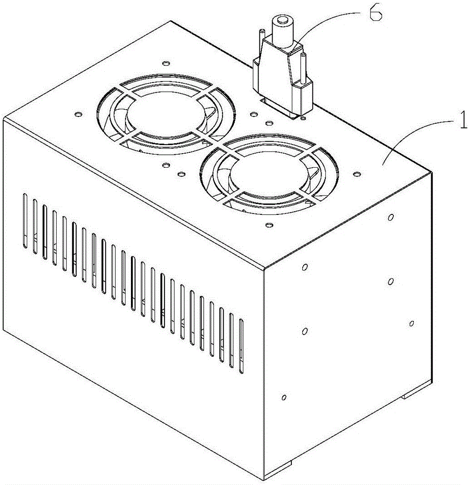
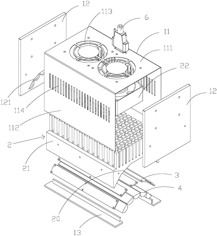
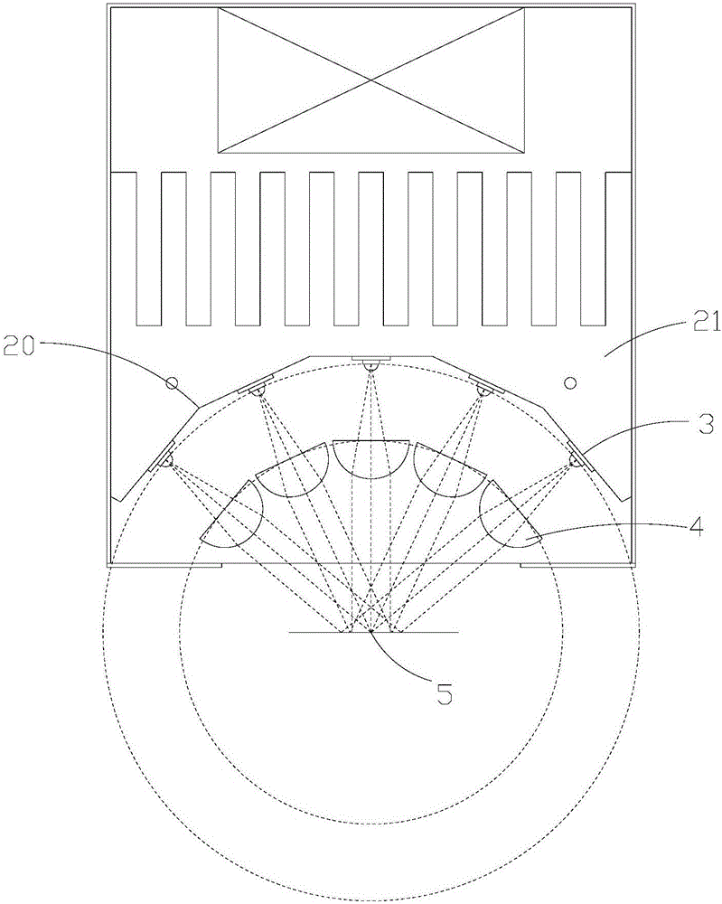
[0019] Such as figure 1 and figure 2 As shown, in some embodiments of the present invention, the UV LED line light source curing machine includes a housing 1 and a heat dissipation device 2 fixedly installed in the housing, several UV LED light source boards 3 and several convex lenses 4, the heat dissipation device 2 A concave surface 20 is formed at the front end of the UV LED light source board 3, and the UV LED light source boards 3 are fixedly installed side by side on the concave surface 20 of the heat sink 2, and the light-emitting axes of the UV LED light source boards 3 converge at a converging point, and each convex lens 4 is correspondingly fixedly installed on the The front end of each UV LED light source plate 3, th...


PUM


Abstract

The invention discloses a UV LED line light source curing machine comprising a shell, a heat dissipating device, a plurality of UV LED light source boards and a plurality of convex lens, wherein the heat dissipating device, the UV LED light source boards and the convex lens are fixedly installed in the shell. The front end of the heat dissipating device forms an inwards recessed face. The UV LED light source boards are fixedly installed on the inwards recessed face of the heat dissipating device side by side, and the light emitting axes of the UV LED light source boards are converged to a convergent point. Each convex lens is correspondingly and fixedly installed at the front end of the corresponding UV LED light source board. The light emitting axis of each UV LED light source board coincides with the main optical axis of the corresponding convex lens, and each UV LED light source board is located at the focus of the corresponding convex lens. The multiple UV LED light source boards and the multiple convex lens are arranged inside the UV LED line light source curing machine, the light emitting axes of the UV LED light source boards and the main optical axes of the convex lens are converged to one point, light sources of the UV light source boards are refracted into parallel light through the convex lens and converged, the illumination intensity at the convergent portion is high, and user demands are met.

Description

technical field [0001] The invention relates to the technical field of ultraviolet curing, in particular to a UV LED line light source curing machine. Background technique [0002] After the UV LED point light source in the IT electronics manufacturing industry, the linear UV LED ultraviolet curing light source has emerged. Unlike the scattered light emitted by the mercury lamp, the ultraviolet light emitted by the UV LED line light source is a narrow linear light that is close to parallel light. It is favored by users for its advantages of energy concentration, high irradiation intensity and high curing efficiency. [0003] However, the current users have higher and higher requirements for the irradiation intensity of the line light source, and hope that the UV LED line light source can provide as high irradiation intensity as possible. At present, some users use the method of increasing the power to enhance the irradiation intensity of UV-LED line light source, but due to...

Claims


Application Information

Patent Timeline
IPC IPC(8): B05D3/06
CPCB05D3/067
Inventor 张炳忠刘新
Owner SHENZHEN RUNWO AUTOMATION ENG CO LTD
Why Eureka
Try Eureka