Automatic tool die changing type special-shaped material blanking machine

A technology of automatic tool changing and blanking machine, applied in metal processing equipment, forming tools, manufacturing tools, etc., can solve the problems of unstable product quality, inaccurate processing stations, waste of too much time, etc., to achieve reasonable structure, Time-saving and easy-to-use effects

Active Publication Date: 2017-05-31
YANCHENG HUASEN MACHINERY
View PDF7 Cites 8 Cited by
  • Summary
  • Abstract
  • Description
  • Claims
  • Application Information

AI Technical Summary

Problems solved by technology

[0002] The punching machine is an indispensable equipment in some light industries. The punching machine is a machine that presses the die with the help of the movement of the machine to cut and process the material. The die of the cutting machine is generally fixed on the punching head. , can only be cut at a fixed position, and the cutter die cannot be changed. If there are different types of cutter heads that need to be replaced, the operator needs to manually replace each action, adjust the position and angle, and waste too much time. The work intensity is high. With the development of society, customers now require small batches and multiple varieties, so it is necessary to constantly replace the cutting die to meet customer needs. The current cutting machine has undergone technological innovation, and the knife can be replaced through the rack and pinion mechanism. However, the existing die changing mechanism has several defects: 1. The position of the die changing mechanism is fixed, and the stamping head must stop at the designated position when changing the die, which is inconvenient to use; 2. The existing die changing mechanism is a rack and pinion mechanism, which has a complex structure and troublesome maintenance. 3. After the die is replaced, there will be displacement during the movement or rotation, resulting in inaccurate processing positions and unstable product quality. Improvements to existing structures

Method used


Image

  • Automatic tool die changing type special-shaped material blanking machine
  • Automatic tool die changing type special-shaped material blanking machine
  • Automatic tool die changing type special-shaped material blanking machine

Examples


Embodiment Construction

[0025] The present invention will be further explained below in conjunction with the accompanying drawings and specific embodiments. It should be understood that the following specific embodiments are only used to illustrate the present invention and are not intended to limit the scope of the present invention. It should be noted that the words "front", "rear", "left", "right", "upper" and "lower" used in the following description refer to the directions in the drawings, and the words "inner" and "outer ” refer to directions towards or away from the geometric center of a particular part, respectively.

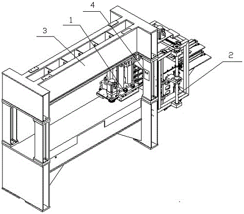
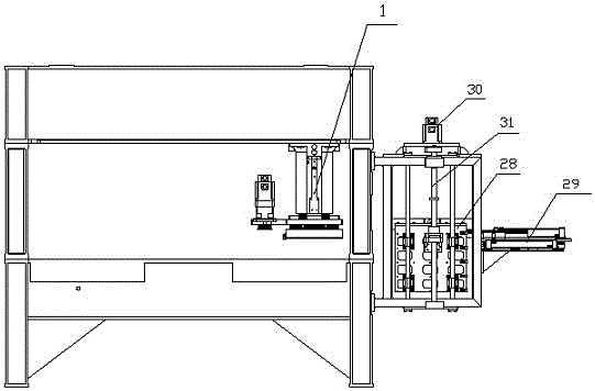
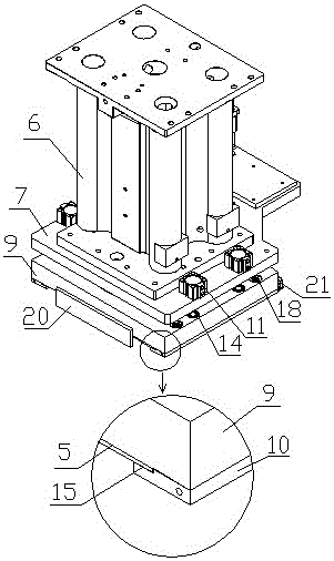
[0026] As shown in the figure, the special-shaped material punching machine with automatic tool change mode according to the present invention includes a punching head 1, a tool changing die mechanism 2, a frame 3, and a control box 4, and the punching head 1 is arranged on the frame 3 , A knife mold 5 is arranged under the stamping head 1, the tool changing mechanism 2 is arra...


PUM


Abstract

The invention discloses an automatic tool die changing type special-shaped material blanking machine which comprises a punching head, a tool die changing mechanism, a rack and a control box. The punching head is arranged on the rack, and a tool die is arranged below the punching head. The tool die changing mechanism is arranged on one side of the punching head, the control box is arranged on the rack, and the tool die changing mechanism can be used for driving the tool die to move between the punching head and a tool die warehouse and be positioned. The clamping effect of a tool die arranged after changing is good, the structure is reasonable, operation is convenient, tool die positioning is accurate, time is saved, the work efficiency is improved, and in addition, the blanking precision is improved.

Description

technical field [0001] The invention belongs to the technical field of punching machines, and in particular relates to a punching machine for special-shaped materials with an automatic tool change mode. Background technique [0002] The punching machine is an indispensable equipment in some light industries. The punching machine is a machine that presses the die with the help of the movement of the machine to cut and process the material. The die of the cutting machine is generally fixed on the punching head. , can only be cut at a fixed position, and the cutter die cannot be changed. If there are different types of cutter heads that need to be replaced, the operator needs to manually replace each action, adjust the position and angle, and waste too much time. The work intensity is high. With the development of society, customers now require small batches and multiple varieties, so it is necessary to constantly replace the cutting die to meet customer needs. The current cutt...

Claims


Application Information

Patent Timeline
Patent Type & Authority Applications(China)
IPC IPC(8): B21D28/02B21D37/04B21D37/14
CPCB21D28/02B21D37/04B21D37/14B21D37/145
Inventor 韦杰韦金权蔡国靖
Owner YANCHENG HUASEN MACHINERY
Why Eureka
Try Eureka