Punching device

A punching device and punching hole technology, applied in the field of punching devices, can solve problems such as workpiece misalignment, low punching efficiency, and reduced workpiece positioning accuracy

Active Publication Date: 2017-05-31
台山市汇铭五金压铸有限公司
View PDF11 Cites 4 Cited by
  • Summary
  • Abstract
  • Description
  • Claims
  • Application Information

AI Technical Summary

Problems solved by technology

However, since the stamping device can only stamp one workpiece at a time, its stamping efficiency is low
In the stamping process, the workpiece is often misaligned, which reduces the positioning accuracy of the workpiece

Method used


Image

  • Punching device
  • Punching device
  • Punching device

Examples


Embodiment Construction

[0018] In order to make the above objects, features and advantages of the present invention more comprehensible, specific implementations of the present invention will be described in detail below in conjunction with the accompanying drawings. In the following description, numerous specific details are set forth in order to provide a thorough understanding of the present invention. However, the present invention can be implemented in many other ways different from those described here, and those skilled in the art can make similar improvements without departing from the connotation of the present invention, so the present invention is not limited by the specific implementations disclosed below.

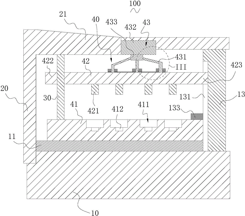
[0019] The invention relates to a stamping device. The stamping device includes a base, a support seat, a guide rod and a stamping assembly. A workbench is arranged on the base, the support seat is arranged on one side of the base, and a support portion is formed on the top of the sup...


PUM

PropertyMeasurementUnit
thicknessaaaaaaaaaa
thicknessaaaaaaaaaa
thicknessaaaaaaaaaa

Abstract

The invention relates to a punching device which comprises a base, a supporting seat, a guide rod and a punching component. A workbench is arranged on the base, a supporting portion is formed at the top of the supporting seat, the punching component comprises a first die holder, a second die holder and a driving member, the first die holder is arranged on the workbench, and the driving member comprises multiple driving portions which are arranged at intervals and connected onto the second die holder. Multiple positioning grooves are formed in the first die holder, a punching hole is formed in the middle of the undersurface of each positioning groove, a positioning ring groove is formed around each positioning groove, multiple positioning columns are arranged in each positioning ring groove, and multiple punches are arranged on the second die holder and respectively align the punching holes in the positioning grooves. The punching device is accurate in positioning and high in punching efficiency.

Description

technical field [0001] The invention relates to a stamping device. Background technique [0002] In industrial production, it is often necessary to punch workpieces. And in order to realize above-mentioned punching operation, need adopt punching device to realize. The stamping device generally includes a base, a support seat, a guide rod and a stamping assembly, a worktable is arranged on the base, the support seat is arranged on the workbench, the guide rod is arranged adjacent to the support seat, and the The stamping assembly includes a first mold base, a second mold base and a driving member, the first mold base is arranged on the workbench, the driving member is arranged on the support base, and the second mold base is connected to The driving member is sleeved on the guide rod. However, since the stamping device can only stamp one workpiece at a time, its stamping efficiency is low. In the stamping process, the workpiece is often misaligned, which reduces the posit...

Claims


Application Information

Patent Timeline
Patent Type & Authority Applications(China)
IPC IPC(8): B21D28/34B21D37/16B21D37/18B21D43/00B21D45/00B21C51/00
CPCB21C51/00B21D28/34B21D37/16B21D37/18B21D43/003B21D45/00
Inventor 黄巧玲
Owner 台山市汇铭五金压铸有限公司
Why Eureka
Try Eureka