Forming dies for stamping and welding parts of pipes for vehicles

A technology for stamping, welding, and forming molds, applied in the field of mold manufacturing, can solve the problems of increased production costs, high size requirements, and low production efficiency, and achieve the effects of reducing sheet springback, dimensional accuracy, and improving production efficiency.

Active Publication Date: 2018-07-13
宁波世纪东港机械有限公司
View PDF6 Cites 0 Cited by
  • Summary
  • Abstract
  • Description
  • Claims
  • Application Information

AI Technical Summary

Problems solved by technology

Although the structure of the sleeve is simple, the size requirements are very high. In the prior art, the processing of the sleeve is various, usually by lathe machining, but the disadvantage of this processing is that the processing of the sleeve usually requires many It is completed in one independent process, from blanking, punching, surface finishing, internal and external surface finishing, surface grinding, etc. These processes involve a variety of fixtures, molds, etc., and almost every process requires a pair of Therefore, on the one hand, the entire production line is equipped with a large number of personnel, resulting in high production costs and low production efficiency; on the other hand, so many molds also increase production costs, and semi-finished products are transported from the previous process to the next process There is a certain positioning error, so the accumulation of errors during production is relatively large, and it is easy to increase the scrap rate of products

Method used


Image

  • Forming dies for stamping and welding parts of pipes for vehicles
  • Forming dies for stamping and welding parts of pipes for vehicles
  • Forming dies for stamping and welding parts of pipes for vehicles

Examples


Embodiment Construction

[0028] The present invention will be described in further detail below in conjunction with the accompanying drawings and specific embodiments.

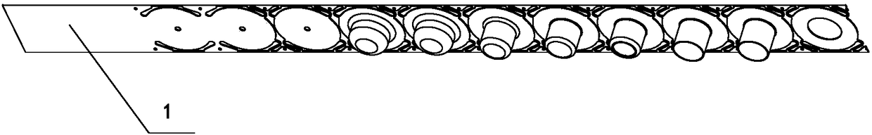
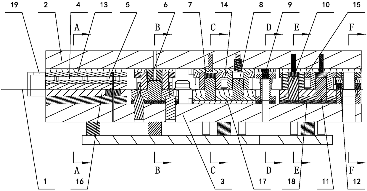
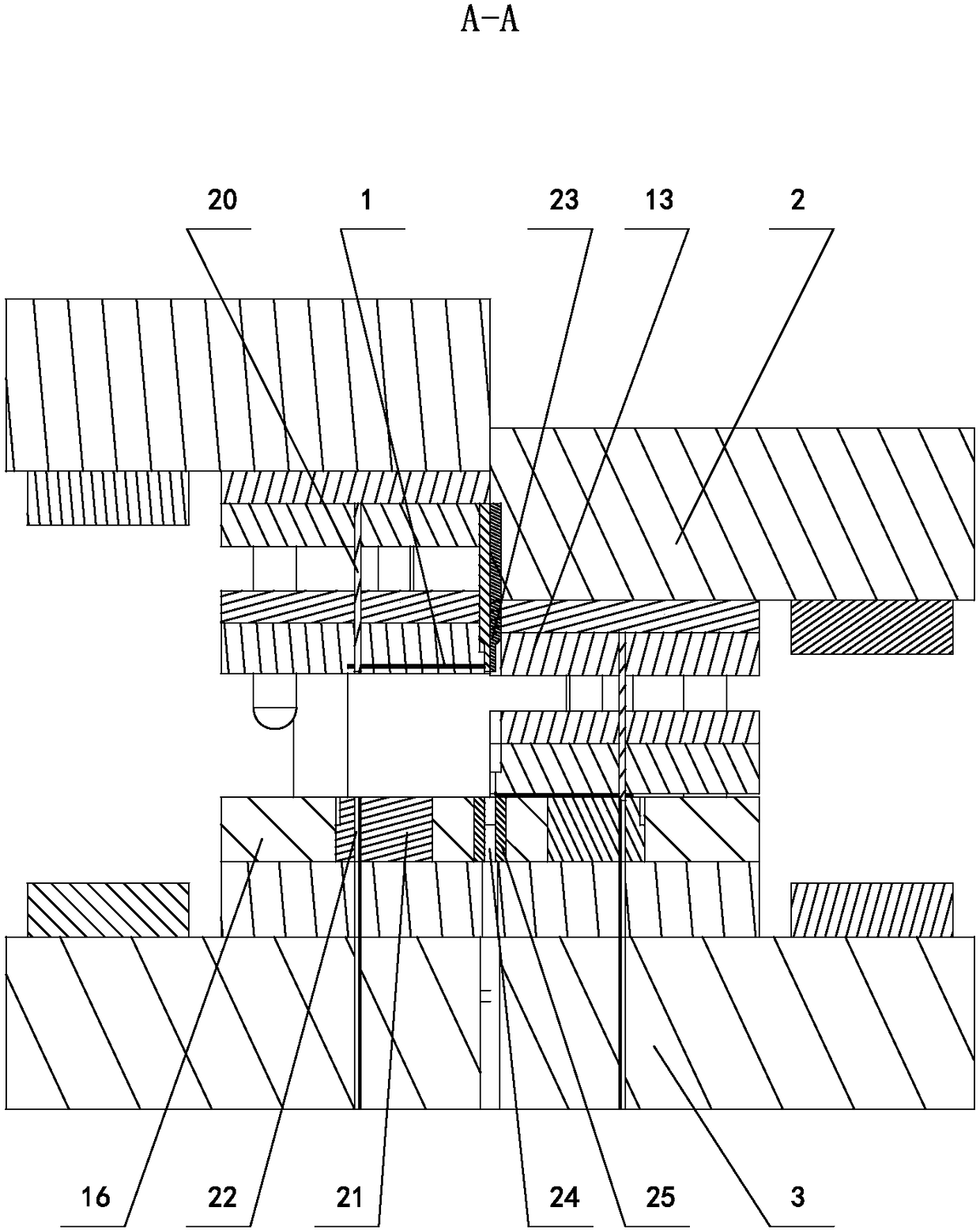
[0029] Depend on Figure 1 to Figure 11 From the structural schematic diagram of the molding die for the stamping and welding parts of the vehicle pipes of the present invention, it can be seen that it includes a lower die assembly, an upper die assembly and a guide assembly connecting the lower die assembly and the upper die assembly. Between the upper mold assembly and the lower mold assembly, an edge punching mechanism 4, an interval punching mechanism 5, a stamping forming mechanism and a shearing forming mechanism 12 are sequentially arranged along a straight line, and the product blank plate 1 passes through the edge punching mechanism 4, The punching mechanism 5, the stamping forming mechanism and the shearing forming mechanism 12 are blanked and formed at intervals. The upper molds of all mechanisms are connected to the same ...


PUM


Abstract

The invention discloses a forming mold of a vehicle tubular punching welding part. The forming mold comprises a lower mold module and an upper mold module; an edge punching mechanism (4), an interval punching mechanism (5), a punching forming mechanism and a shearing forming mechanism (12) are straightly arranged between the upper mold module and the lower mold module in sequence; a product blank plate (1) passes through the edge punching mechanism (4), the interval punching mechanism (5), the punching forming mechanism and the shearing forming mechanism (12) in sequence for blanking formation; upper molds of all mechanisms are all connected to the same one upper mold plate as a large upper mold plate (2), and lower molds of all mechanisms are all connected to the same one lower mold plate as a large lower mold plate (3); the large lower mold plate (3) is fixedly connected to a worktable; and the large upper mold plate (2) is fixedly connected to an output end of a driving part slidingly connected with an equipment frame. After the structure is adopted, the production efficiency is greatly improved, and meanwhile, the number of operators is largely reduced, so that the production cost is reduced.

Description

technical field [0001] The invention relates to the technical field of mold manufacturing, in particular to a forming mold for stamping welded parts of pipes for vehicles. Background technique [0002] There are a variety of spare parts on the car, pipe stamping and welding parts are part of it, and sleeves are the most commonly used parts. Although the structure of the sleeve is simple, the size requirements are very high. In the prior art, the processing of the sleeve is various, usually by lathe machining, but the disadvantage of this processing is that the processing of the sleeve usually requires many It is completed in one independent process, from blanking, punching, surface finishing, internal and external surface finishing, surface grinding, etc. These processes involve a variety of fixtures, molds, etc., and almost every process requires a pair of Therefore, on the one hand, the entire production line is equipped with a large number of personnel, resulting in high...

Claims


Application Information

Patent Timeline
Patent Type & Authority Patents(China)
IPC IPC(8): B21D37/08B21D37/10B21D37/12B21D28/14B21D28/34
CPCB21D28/14B21D28/34B21D37/08B21D37/10B21D37/12
Inventor 葛鹏毅
Owner 宁波世纪东港机械有限公司
Why Eureka
Try Eureka