Riveting stake and automatic drilling riveter

A riveting anvil and claw finger technology, which is applied in the field of upper riveting anvils and automatic drilling and riveting machines, can solve problems such as inability to discharge rivets, achieve the effect of avoiding rivet indentation, and improving riveting quality and efficiency

Active Publication Date: 2017-05-31
AVIC CHENGFEI COMML AIRCRAFT COMPANY
View PDF4 Cites 3 Cited by
  • Summary
  • Abstract
  • Description
  • Claims
  • Application Information

AI Technical Summary

Problems solved by technology

[0005] The present invention provides an upper riveting anvil, aiming to solve the problem that the existing upper riveting anvil cannot discharge redundant rivets when the rivet insertion mechanism sends two rivets into the claws at the same time

Method used


Image

  • Riveting stake and automatic drilling riveter
  • Riveting stake and automatic drilling riveter
  • Riveting stake and automatic drilling riveter

Examples


Embodiment Construction

[0018] The present invention will be further described below in conjunction with accompanying drawing.

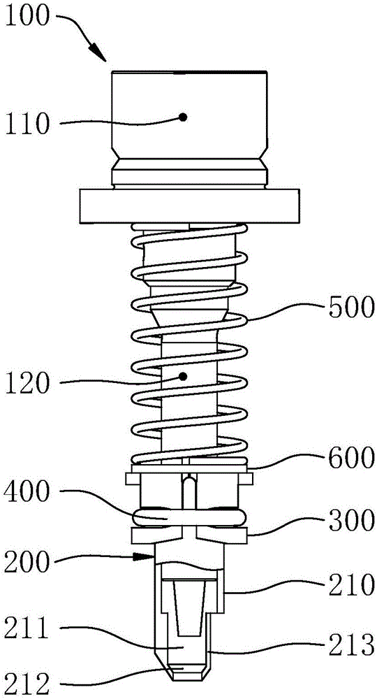
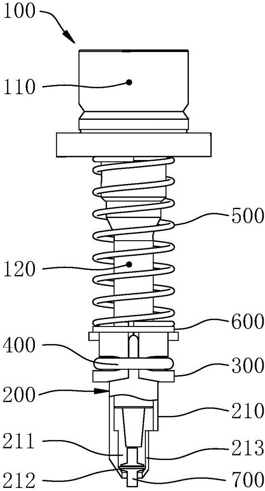
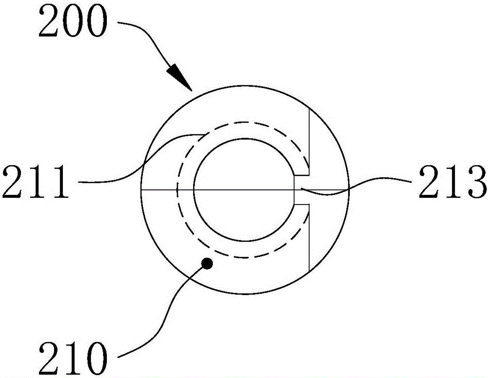
[0019] combine Figure 4 with Image 6 As shown, the upper riveting anvil includes nail claws 200. The nail claws 200 are composed of two claw fingers 210 arranged symmetrically. There is a semi-circular groove 211 on the top, and the semi-circular groove 211 on each claw finger 210 can jointly form a nail groove for clamping the rivet 700 after the two claw fingers 210 are fitted together as a whole. The lower end of the nail groove is tapered One of the seams where the two claw fingers 210 are attached is provided with a nail entry opening 213 connecting the nail groove and the outside world; the other seam where the two claw fingers 210 are attached is provided with an extrusion gap 214, The extrusion notch 214 includes a structural surface perpendicular to the other seam, the structural surface being tangent to the nail groove. The extrusion notch 214 corresponds to ...


PUM


Abstract

The invention discloses a riveting stake and an automatic drilling riveter; the riveting stake and the automatic drilling riveter aim to solve the problems that the existed riveting stake cannot discharge excessive rivets when the rivets are inserted to the mechanism while two rivets are delivered to a rivet pawl. The riveting stake comprises a rivet pawl, wherein the rivet pawl consists of two pawl fingers pasted together, semicircular groves are arranged on the part of every pawl finger for pasting; the semicircular groves on the pawl finger can commonly be encircled to a rivet slot; one joint of two pasted pawl fingers is provided with a rivet feeding opening; the other joint of two pasted pawl fingers is provided with an extruding notch, and the extruding notch comprises a structure face perpendicular to the other joint, the structure face is tangential to the rivet slot. When the rivet inserting mechanism of the automatic drill riveter has the logic failure, and two rivets are feed to the rivet slot, the rivet delivered later can extrude the previous rivet out of the rivet slot through the extruding notch, so residual rivets are discharged, thereby avoiding the rivet indentation on the riveted product and improving the riveting quality and efficiency.

Description

technical field [0001] The invention relates to a riveting drill part and riveting equipment, in particular to an upper riveting anvil and an automatic riveting machine. Background technique [0002] The upper riveting anvil is one of the main parts of the automatic drilling and riveting machine, which is used to receive the rivet and cooperate with the lower riveting anvil to complete the riveting work of the aircraft panel. Such as figure 1 with image 3 As shown, the existing upper riveting anvil includes an upper riveting rod 100 whose upper part is a handle 110 and whose lower part is a rod segment 120. The lower end of the rod segment 120 is provided with nail claws 200, and the nail claws 200 are composed of two claw fingers 210 arranged symmetrically. Composition, the nail claw 200 is provided with a pair of nail claw buckles 300, under the action of the nail claw buckle 300, the two claw fingers 210 can fit together, and each claw finger 210 is provided with a sem...

Claims


Application Information

Patent Timeline
Patent Type & Authority Applications(China)
IPC IPC(8): B21J15/14B21J15/32B23P23/04
CPCB21J15/142B21J15/32B23P23/04
Inventor 余湘锦马长春王彩云
Owner AVIC CHENGFEI COMML AIRCRAFT COMPANY
Why Eureka
Try Eureka