Casting method for directional solidification column crystal and single-crystal blade

A single crystal blade, directional solidification technology, applied in the field of investment precision casting, can solve the problem of thin edge plate looseness, etc., and achieve the effect of improving the feeding capacity

Active Publication Date: 2017-05-31
AECC AVIATION POWER CO LTD
View PDF8 Cites 8 Cited by
  • Summary
  • Abstract
  • Description
  • Claims
  • Application Information

AI Technical Summary

Problems solved by technology

[0007] Aiming at the deficiencies in the prior art, the purpose of the present invention is to propose a casting method for directionally solidified columnar crystals and single crystal blades. Through process feeding ribs, the part of the edge plate that is prone to loosening is connected with the ingate, and the edge of the blade is The metal shrinkage during the directional solidification process of the plate is compensated, and the problem of looseness of the larger and thinner edge plate on the blade is solved

Method used


Image

  • Casting method for directional solidification column crystal and single-crystal blade

Examples


Embodiment Construction

[0032] Below in conjunction with specific embodiment the present invention is described in further detail:

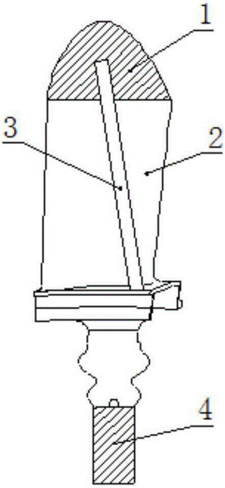
[0033] Such as figure 1 As shown, when the blade wax model is trimmed and assembled, one end of the process feeding rib is bonded to the inner gate of the upper end of the blade, basically parallel to the blade body, and the gap between the blade body and the blade body is more than 8mm, and the other end is bonded to the corner of the edge plate , The position determination principle is that at the corner of the edge plate farthest from the blade body, and at the connection with the edge plate, a 1-2mm cutting section should be reserved. The width and thickness of the cutting section can be greater than or equal to the process feeding rib. Process feeding bars can be cylindrical process bars with a diameter of about Φ3mm, and flat process feed bars with a thickness of 0.5 mm to 1 mm and a width of 3 mm to 6 mm. The process feeding ribs cannot be straightened and tight...


PUM

PropertyMeasurementUnit
thicknessaaaaaaaaaa
thicknessaaaaaaaaaa
widthaaaaaaaaaa

Abstract

The invention discloses a casting method for a directional solidification column crystal and a single-crystal blade. During finishing combination of a blade wax mold, one end of a technology feeding rib is stuck to an inner gate of the upper end of the blade, and the other end of the technology feeding rib is stuck to the position of the farthest corner, away from a blade body, of an edge plate. The technology feeding rib is parallel to the blade body so that molten metal can reach the position of the thin corner of a casting during pouring, the feeding capability of the casting is improved, and the problem of the porosity defect caused by the fact that cooling is conducted too fast and feeding cannot be conducted in time in the solidification process of the thin and large blade edge plate with a suddenly-changed section is solved.

Description

[0001] 【Technical field】 [0002] The invention belongs to the field of precision investment casting and relates to a casting method for directional solidification column crystals and single crystal blades. [0003] 【Background technique】 [0004] The edge plate of the blade has a sudden change section and is too thin and too large. Due to this structure, it often cools too fast during the solidification process, and it is too late to feed, resulting in the loose defect of the edge plate. [0005] The common solutions at present: one is to wrap ceramic wool on the edge of the formwork to reduce its cooling rate, but for larger and thinner edge plates, the effect is not obvious; the second method is to increase the pouring temperature, but it will bring leaves The metallurgical defects of other parts such as body and mortise; the third method is to set up a hidden riser in the loose part to increase feeding, but there is no continuous metal feeding channel, and the improvement e...

Claims


Application Information

Patent Timeline
Patent Type & Authority Applications(China)
IPC IPC(8): B22C9/04C30B11/00
CPCB22C9/04C30B11/00
Inventor 董茵常涛岐李琳马成陈杰
Owner AECC AVIATION POWER CO LTD
Why Eureka
Try Eureka