
Gear ring casting method

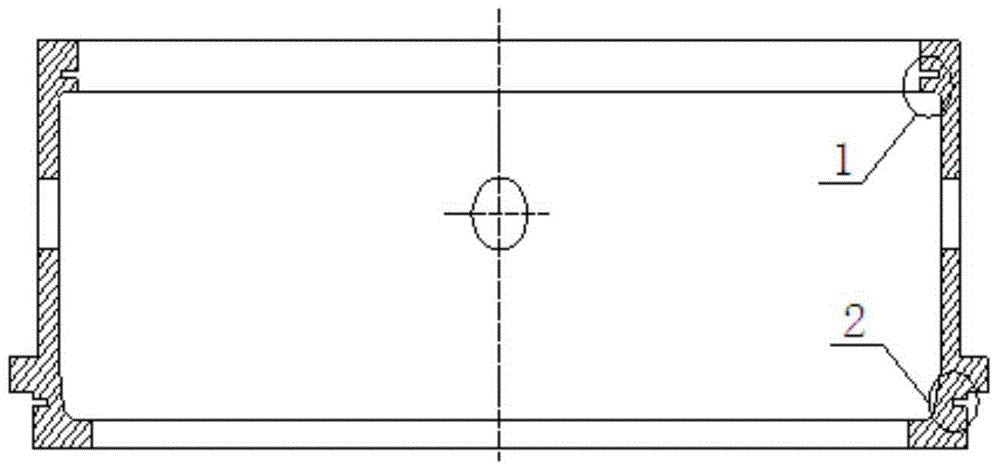
A ring gear and ring technology, applied in the direction of casting molding equipment, casting molds, casting mold components, etc., can solve problems such as the inability to effectively solve loose defects at the undercut, increase the modulus of the feeding part, and reduce the yield of the process. To achieve the effect of facilitating the floating of impurities, ensuring filling and fluidity

Active Publication Date: 2015-08-12
四川共享铸造有限公司
View PDF7 Cites 9 Cited by
  • Summary
  • Abstract
  • Description
  • Claims
  • Application Information

AI Technical Summary

Problems solved by technology

[0004] The casting process of most manufacturers usually adopts the bottom injection anti-rain pouring system, and the top is equipped with riser feeding, and strives to adopt the principle of directional solidification to make the casting structure compact. However, this process still cannot effectively solve the loose defects of the undercut.
The reason is that the parts where the defects occur are all in the above-mentioned hot spot area, and cannot get enough liquid replenishment in the later stage of solidification. Although the top riser is used for feeding, the unreasonable setting of the parameters and position of the riser increases the stress of the feeding part. Modulus, new porosity is generated at the root of the riser, and the process yield is reduced

Method used


Image

  • Gear ring casting method
  • Gear ring casting method
  • Gear ring casting method

Examples


Embodiment Construction

[0023] In order to enable those skilled in the art to better understand the technical solutions of the present invention, the present invention will be further described in detail below in conjunction with specific examples.

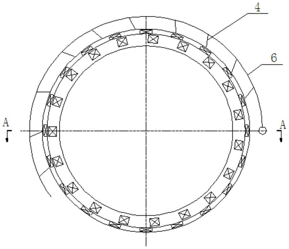
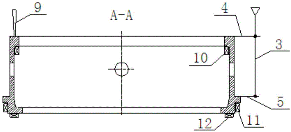
[0024] Such as figure 2 , image 3 As shown, a casting method of a ring gear, the sand mold of the ring gear casting adopts upper, middle and lower three-box molding, and the sand mold includes a sprue 3, an upper inner runner 4, a lower inner runner 5, an upper inner runner Annular runner 6, the lower annular runner (not shown in the figure), the upper annular runner 6 communicates with one end of the upper inner runner 4, and the other end of the upper inner runner 4 communicates with The sand mold cavity is communicated, the lower annular runner (not shown) is communicated with one end of the lower inner runner 5, and the other end of the lower inner runner 5 is communicated with the sand mold cavity , the sprue 3 is vertically arranged on the oute...


PUM

PropertyMeasurementUnit
hardnessaaaaaaaaaa
widthaaaaaaaaaa
depthaaaaaaaaaa

Abstract

The invention discloses a gear ring casting method. A sand mold comprises a sprue, an upper layer ingate, a lower layer ingate, an upper layer annular runner and a lower layer annular runner, wherein the upper layer annular runner is communicated with one end of the upper layer ingate, the other end of the upper layer ingate is communicated with the mold cavity of the sand mold; the lower layer annular runner is communicated with one end of the lower layer ingate, the other end of the lower layer ingate is communicated with the mold cavity of the sand mold; the sprue is vertically arranged at the outer side surface of the sand mold and is in parallel to the bus of the sand mold; the sprue is separately communicated with the upper and lower layer annular runners; at least one vent sheet is arranged on the upper surface of the sand mold; and at least one cold iron is arranged at the hot section zone of the gear ring. The problem of structure loosening defects of the tooth insertion part and blade withdrawal groove of the gear ring in the prior art is solved, the casting body fits the technical requirement and the process yield reaches 85.5%.

Description

technical field [0001] The invention relates to the casting field of nodular cast iron castings, in particular to a sand casting method for a nodular cast iron ring gear. Background technique [0002] Offshore wind energy resources are abundant and less affected by the environment. Offshore wind farms are currently a rapidly developing market with broad prospects. However, complex offshore natural conditions keep the failure rate of wind turbines at a high level, and the quality of the ring gear is the cause of failure. one of the reasons. At present, the material of the ring gear casting is mainly QT400-18L, and the maximum outline size of the casting is φ1800×580. The casting transmits torque through the meshing of the upper and lower ends of the internal and external teeth. The working environment of the ring gear casting is harsh, the working temperature ranges from -45°C to 45°C, and it is exposed to corrosive, salt spray, and sandstorm environments for a long time. T...

Claims


Application Information

Patent Timeline
Patent Type & Authority Applications(China)
IPC IPC(8): B22C9/24B22C9/20B22C9/02
Inventor 陈勇李小静
Owner 四川共享铸造有限公司
Learn More