

Combined calender roll for papermaking calender
A combined calender roll technology, which is applied to paper machines, calenders, papermaking, etc., can solve the problems of roll body porosity, difficult feeding, sand holes, etc., so as to save metal materials, improve roll surface quality, and reduce roll damage. The effect of body weight
- Summary
- Abstract
- Description
- Claims
- Application Information
AI Technical Summary
Problems solved by technology
Method used
Image

Examples
Embodiment Construction
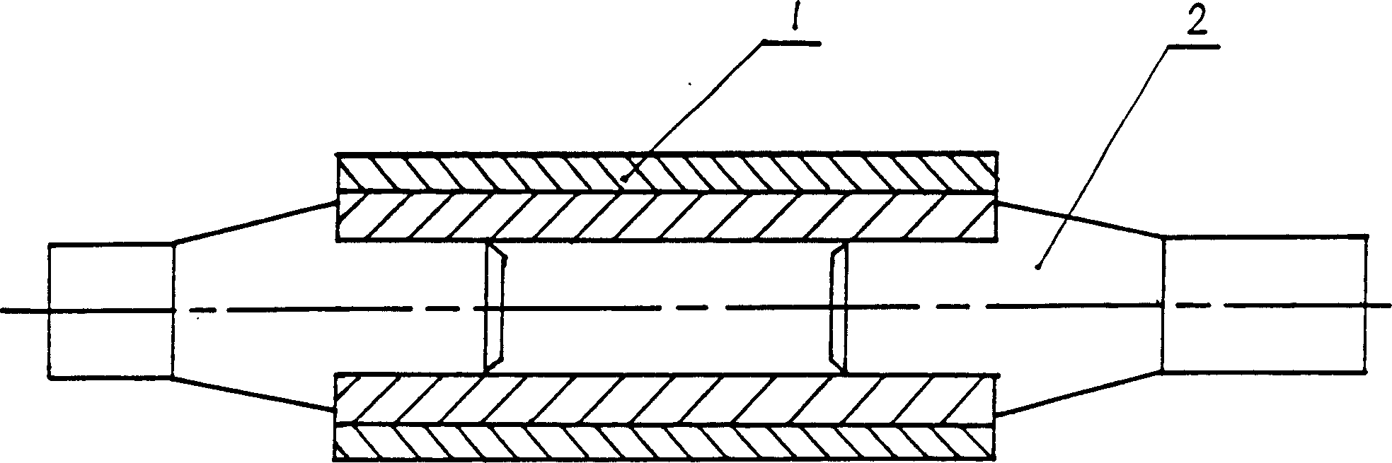
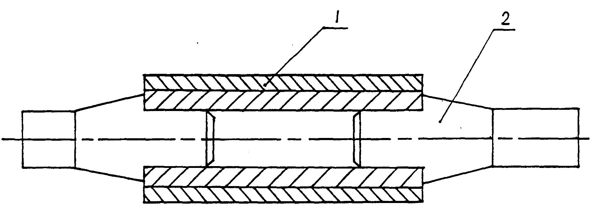
[0011] figure 1 It is a combined calender roll assembled by shrink-fitting. The roll sleeve 1 and roll shaft 2 are assembled and fixed by the interference to bear the working pressure.
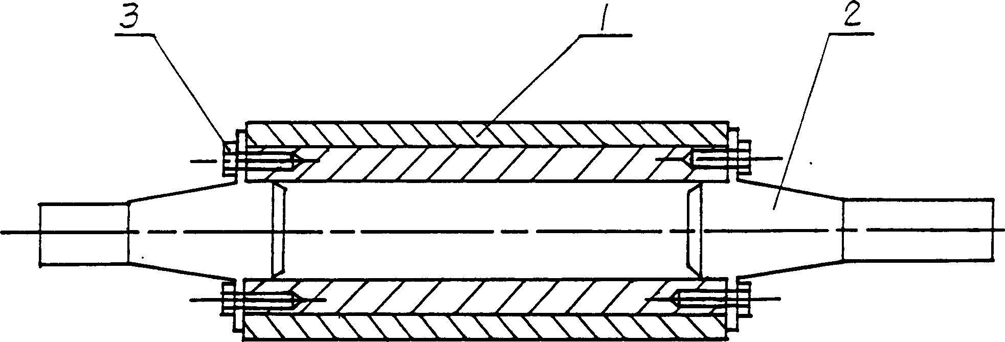
[0012] figure 2 It is a combined calender roll assembled in the way of 3 bolts, and the threaded hole is set on the inner metal part of the roll sleeve, which is convenient for processing.
[0013] The combined calender rolls for papermaking calenders produced according to the above-mentioned technical scheme completely eliminate various casting defects of the roll body and neck, and significantly improve the quality of the calender rolls, especially for the longer roll surfaces that have been used more in recent years ( 2000mm~10000mm) calender rolls, the combined calender rolls of the present invention show great advantages.
PUM
 Abstract
Description
Claims
Application Information