Tubular part welding clamping device

A technology of pipe parts and welding clamps, which is applied in the direction of auxiliary devices, welding equipment, auxiliary welding equipment, etc., can solve the problems of unsatisfactory positioning and clamping effect of steel pipes, inability to realize flexible adjustment, and affecting the quality and performance of welding projects, etc. , to achieve the effect of simple adjustment and precise docking

Inactive Publication Date: 2017-05-31
宁波东方电缆股份有限公司
View PDF8 Cites 29 Cited by
  • Summary
  • Abstract
  • Description
  • Claims
  • Application Information

AI Technical Summary

Problems solved by technology

However, for the current existing welding fixtures for pipe parts, it is not possible to achieve flexible adjustments (especially fine-tuning in position) when clamping and aligning pipe par

Method used


Image

  • Tubular part welding clamping device
  • Tubular part welding clamping device
  • Tubular part welding clamping device

Examples


Embodiment 1

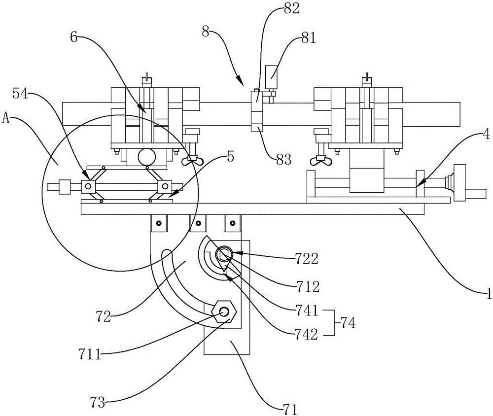
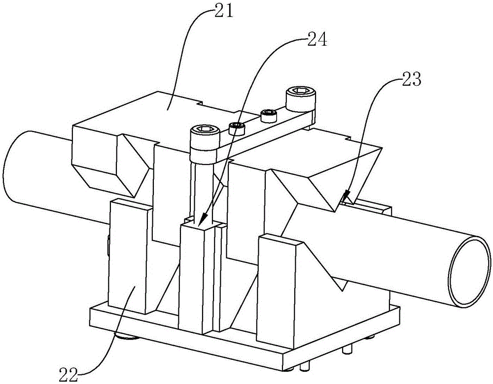
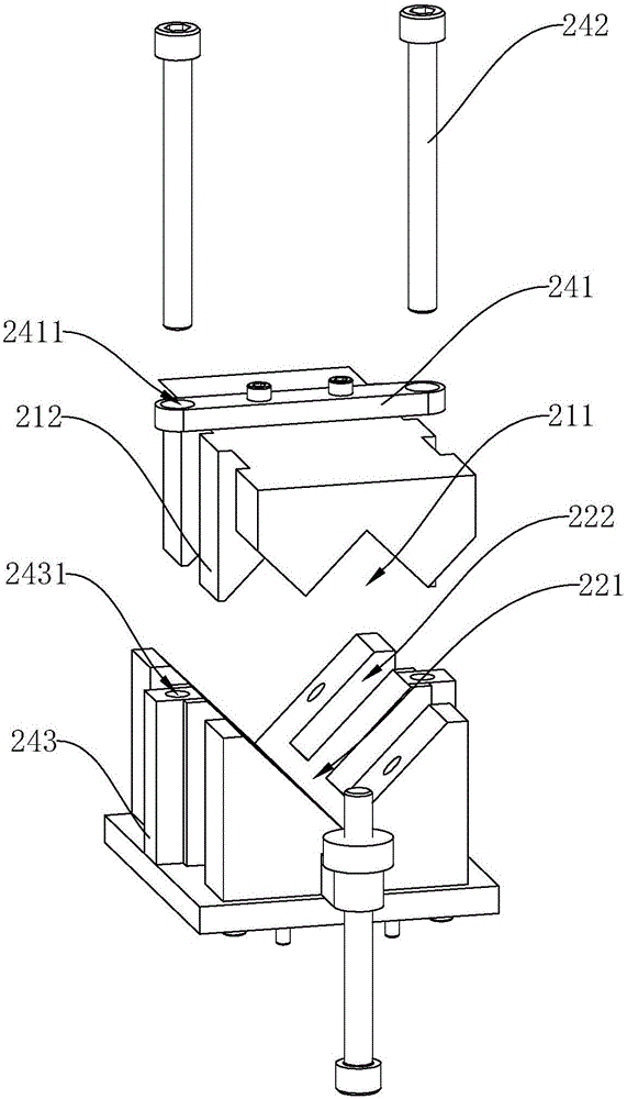
[0023] Embodiment 1: As shown in the figure, a welding and clamping device for pipe parts includes a workbench 1 on which a first clamping mechanism 2 for clamping a first pipe 91 and a first clamping mechanism for clamping a first pipe 91 are arranged. The second clamping mechanism 3 of the second pipe 92, the first adjusting mechanism 4 is arranged between the first clamping mechanism 2 and the workbench 1, and the first adjusting mechanism 4 is used to drive the first clamping mechanism 2 along the workbench 1. The length direction is displaced left and right, the workbench 1 is also provided with a second adjustment mechanism 5, the second adjustment mechanism 5 is provided with a third adjustment mechanism 6, the second clamping mechanism 3 is arranged on the third adjustment mechanism 6, and the second adjustment mechanism The mechanism 5 is used to drive the third adjusting mechanism 6 to move up and down along the height direction of the workbench 1 , and the third adju...

Embodiment 2

[0027] Embodiment 2: As shown in the figure, a welding and clamping device for pipe parts includes a workbench 1 on which a first clamping mechanism 2 for clamping a first pipe 91 and a first clamping mechanism 2 for clamping a first pipe 91 are arranged. The second clamping mechanism 3 of the second pipe 92, the first adjusting mechanism 4 is arranged between the first clamping mechanism 2 and the workbench 1, and the first adjusting mechanism 4 is used to drive the first clamping mechanism 2 along the workbench 1. The length direction is displaced left and right, the workbench 1 is also provided with a second adjustment mechanism 5, the second adjustment mechanism 5 is provided with a third adjustment mechanism 6, the second clamping mechanism 3 is arranged on the third adjustment mechanism 6, and the second adjustment mechanism The mechanism 5 is used to drive the third adjusting mechanism 6 to move up and down along the height direction of the workbench 1 , and the third ad...


PUM


Abstract

The invention discloses a tubular part welding clamping device which comprises a working table, wherein a first clamping mechanism for clamping a first pipe fitting and a second clamping mechanism for clamping a second pipe fitting are arranged on the working table; a first adjusting mechanism is arranged between the first clamping mechanism and the working table and is used for driving the first clamping mechanism to move left and right in the length direction of the working table; a second adjusting mechanism is further arranged on the working table; a third adjusting mechanism is arranged on the second adjusting mechanism; the second clamping mechanism is arranged on the third adjusting mechanism; the second adjusting mechanism is used for driving the third adjusting mechanism to move up and down in the height direction of the working table; and the third adjusting mechanism is used for driving the second clamping mechanism to move front and back in the width direction of the working table. The tubular part welding clamping device has the advantages of being convenient and reliable in positioning and flexible in adjustment.

Description

technical field [0001] The invention relates to a clamping device, in particular to a welding clamping device for pipe parts. Background technique [0002] During the use of pipe parts, sometimes it is necessary to weld two pipe fittings together, especially parts such as steel pipes, to meet the requirements of different lengths and performances. In the welding process, two people are usually required to operate together. One person holds the steel pipe and rotates it, and the other holds a welding torch to weld the joint of the steel pipe. The welding process is time-consuming and labor-intensive. A large error will affect the welding quality, and then affect the service life after welding. [0003] There are also some clamping equipment used for welding on the market. However, for the current existing welding fixtures for pipe parts, it is not possible to achieve flexible adjustments (especially fine-tuning in position) when clamping and aligning pipe parts, and the pos...

Claims


Application Information

Patent Timeline
IPC IPC(8): B23K37/053
CPCB23K37/0533
Inventor 钟科星陈凯胡一鸣
Owner 宁波东方电缆股份有限公司
Why Eureka
Try Eureka