

Mechanical part machining method
A technology of mechanical parts and processing methods, which is applied in the field of processing of mechanical parts, can solve the problems of high cost and achieve the effects of cheap price, simple drilling operation and reduced cutting allowance
Inactive Publication Date: 2017-05-31
黑龙江万向鹏程科技发展有限公司
View PDF0 Cites 0 Cited by
- Summary
- Abstract
- Description
- Claims
- Application Information
AI Technical Summary
Problems solved by technology
It is expensive to buy a new milling cutter, and this method can only process about 3 pieces an hour
Method used
View moreImage
Smart ImageViewing Examples

Examples
Embodiment Construction
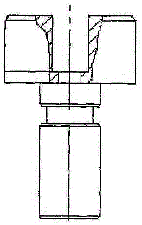
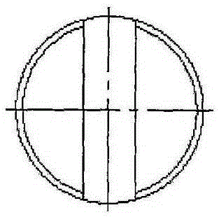
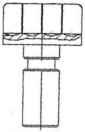
[0012] choose as figure 1 and figure 2 For the part to be processed as shown, the groove depth required on the part is 25, and the width is 16. Use a drill to drill 4 holes of ¢14, and the hole depth is 23.5, such as image 3 , Figure 4 As shown, milling with a milling cutter again, because the cutting allowance is greatly reduced, the milling cutter can be milled to the size at one time, and the two processes of drilling and milling are about 7-8 minutes with clamping.
Login to View More PUM
 Abstract
The invention discloses a mechanical part machining method. A machining method of a groove in a mechanical part comprises the following steps: a plurality of holes are firstly drilled by a drilling machine; most cutting quantities are taken away; and then, a milling tool is used for once milling to reach a needed size. The aperture of the drilled holes is slightly smaller than the width of the groove; and the depth of the holes is slightly smaller than the depth of the groove. In the new process, a plurality of holes are firstly drilled by the drilling machine, and most cutting quantities are taken away, so that the cutting allowance is largely reduced, and the milling tool can once mill to reach the needed size. Two procedures of drilling and milling including clamping need about 7-8 minutes. From the aspect of wear of the tool, after the new process is adopted to machine more than 800 products, the milling tool is not narrowed, and the only change is that the back angle of the milling tool is blunt, so that the milling tool can be continuously used only through grinding the back angle by operators. Drilling bits for drilling are lower in cost; and the drilling operation is simpler. The new process is unanimously praised by the operators.
Description
technical field [0001] The invention relates to the technical field of mechanical processing, in particular to a processing method of mechanical parts. Background technique [0002] In the existing mechanical processing, the slotting on the parts is generally completed by a milling machine. For example, to process a figure 1 , figure 2 The groove on the part shown is 25 deep and 16 wide. First, use the rough milling cutter to mill 5 times, and then use the fine milling cutter to mill once. Although this processing method can meet the precision requirements, due to the large amount of cutting, When a new milling cutter reaches about 200 pieces, its width becomes narrower. It is expensive to buy a new milling cutter, and this method can only process about 3 parts an hour. Therefore, it is uneconomical in terms of saving man-hours and reducing tool costs, and a new method is urgently needed to replace it. Contents of the invention [0003] The object of the present inve...
Claims
Login to View More Application Information
Patent Timeline
 Patent Type & AuthorityApplications(China)
IPC IPC(8): B23P15/00
CPCB23P15/00
Inventor不公告发明人
Owner黑龙江万向鹏程科技发展有限公司