A special-shaped movable corner code processing device

A processing device and corner code technology, which is applied in the direction of manufacturing tools and other manufacturing equipment/tools, etc., can solve the problems of manual assisted clamping, easy hand clamping, inability to use punching device processing, and low degree of automation, so as to achieve broad processing range, save manpower and material resources, and have a high degree of mechanization

Active Publication Date: 2019-11-22
济南温豆斯机械设备有限公司
View PDF7 Cites 0 Cited by
  • Summary
  • Abstract
  • Description
  • Claims
  • Application Information

AI Technical Summary

Problems solved by technology

[0004] like figure 2 As shown, it is the profile of the special-shaped movable corner bracket. At present, the connection holes on the concave limb of the special-shaped movable corner bracket and the round holes on the convex limb are mainly processed by manual drilling. Since the convex limb of the special-shaped movable corner bracket is closed, so It is impossible to use a punching device for processing. At present, the processing of special-shaped movable corners is mainly carried out by manual drilling. Every time a special-shaped movable processing is processed, clamping and positioning must be performed twice, that is, clamping and positioning once when processing the connecting hole. Clamp and position once when processing the round hole, and then use the drilling tool to process the connecting hole and the round hole respectively. The above-mentioned processing method has low automation, low processing accuracy, low processing efficiency, and manual auxiliary Risks such as pinching are prone to occur

Method used


Image

  • A special-shaped movable corner code processing device
  • A special-shaped movable corner code processing device
  • A special-shaped movable corner code processing device

Examples


Embodiment Construction

[0031] Below in conjunction with accompanying drawing and embodiment the present invention will be further described:

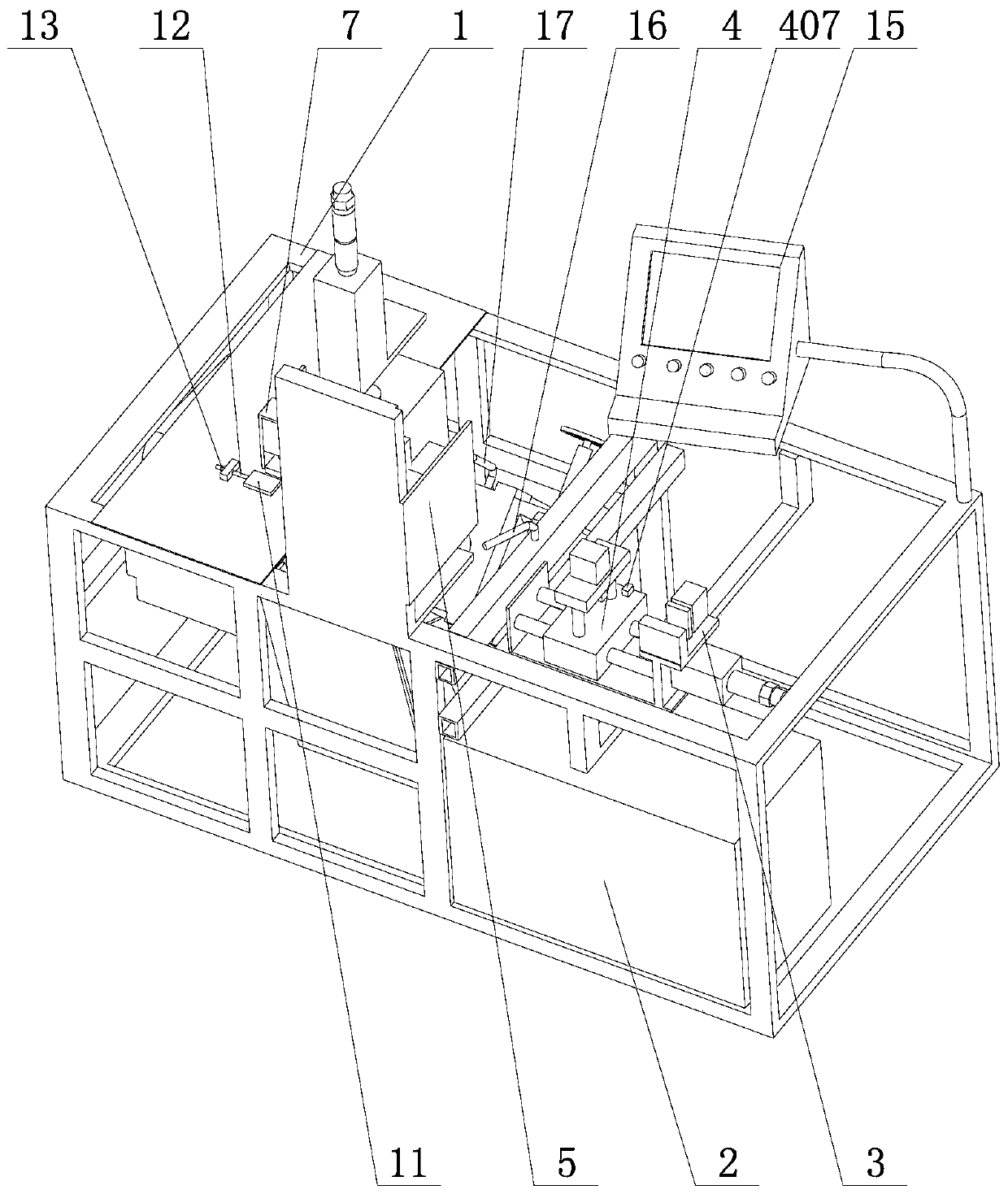
[0032] Such as Figure 1-5 As shown, a special-shaped movable corner code processing device includes a workbench 1, on which along the direction of travel of the special-shaped movable corner code profiles, an auxiliary clamp 3, a conveyor 4, and a drill are respectively connected to the control box 2. Hole mechanism 5 and cutting machine 6, one end of workbench 1 is provided with auxiliary clamp 3, the position close to auxiliary clamp 3 on workbench 1 is provided with conveyer 4, the position close to conveyer 4 is provided on workbench 1 There is a drilling mechanism 5, and a cutting machine 6 is provided on the workbench 1 along the side of the traveling direction of the special-shaped movable corner code profile near the drilling mechanism 5, and the auxiliary clamper 3, conveyor 4, and drilling mechanism 5 are designed and cutting machine 6, realize th...


PUM


Abstract

A special-shaped movable corner brace machining device comprises a workbench. An auxiliary clamping device, a conveying device, a drilling mechanism and a cutting machine are sequentially arranged on the workbench in the advancing direction of special-shaped movable corner brace profiles and are all connected with a control cabinet. The auxiliary clamping device is arranged at one end of the workbench, the conveying device is arranged in the position, close to the auxiliary clamping device, of the workbench, the drilling mechanism is arranged in the position, close to the conveying device, of the workbench, and the cutting machine is arranged in the position, close to the drilling mechanism, of the workbench in the advancing direction of the special-shaped movable corner brace profiles. The special-shaped movable corner brace machining device has the advantages of being high in mechanical degree, production efficiency and machining precision and the like, and the problems in the prior art are solved.

Description

Technical field: [0001] The invention relates to the technical field of corner code processing, in particular to a special-shaped movable corner code processing device. Background technique: [0002] The special-shaped movable corner bracket is a kind of movable corner bracket with the advantages of convenient connection, reliable connection, and low cost. It is used in the field of aluminum doors and windows. The main difference between the special-shaped movable corner bracket and the movable corner bracket is the slide setting of the special-shaped movable corner bracket In the middle of its lugs, the base of the lugs is sealed and therefore cannot be processed by conventional punching machines. [0003] Such as figure 1 As shown, the special-shaped movable corner code includes two parts, the first corner code and the second corner code. The concave limbs of the first corner code and the second corner code are provided with connecting holes for installing bolts and nuts....

Claims


Application Information

Patent Timeline
Patent Type & Authority Patents(China)
IPC IPC(8): B23P23/02
CPCB23P23/02
Inventor 王子扬王浩冉王帅军王全军
Owner 济南温豆斯机械设备有限公司
Why Eureka
Try Eureka